Reaping benefits of radial chip thinning

Author David Conigliaro
Published
March 01, 2014 - 10:45am

The well-established concept of radial chip thinning (RCT) provides compelling productivity-enhancing benefits, but is still not widely applied. RCT occurs when the DOC is less than the radius of a round milling insert and chip thickness is less than the programmed feed per tooth. This means a higher programmed feed rate is needed to achieve a particular chip thickness, measured in ipt. In other words, the programmed feed rate can be higher because of chip thinning.

Many programmers and machinists are afraid to increase the feed, a fear usually based on an unfortunate previous experience. However, the industry trend is to step-down significantly deeper during machining, greatly reducing step-over. Step-overs have been typically much more than 50 percent of a tool’s width because end users tend to take shallow step-downs, whereas deep step-downs require reduced step-overs. It’s important to note RCT doesn’t comes into play when applying less than half the tool’s width.

Dynamic.tif
Traditional.tif

Images courtesy of CNC Software

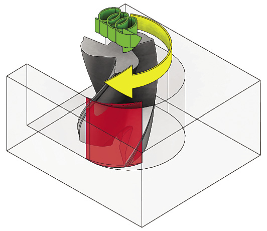
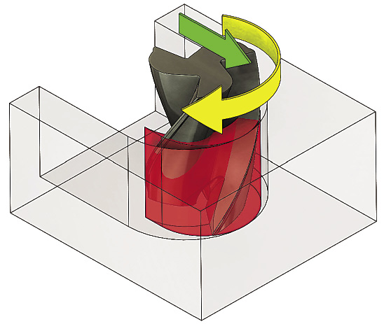
Toolpaths programmed with Mastercam’s Dynamic Machining suite produce radial chip thinning (top), whereas a traditional toolpath (above) doesn’t enable the productivity-enhancing benefits RCT provides.

New CAM toolpaths and cutting tool designs, such as those used in Mastercam’s Dynamic Machining suite and Iscar’s High-Efficiency Machining tools, push the advantages of RCT to its practical limit. None of this was possible until all the elements—including cutting tools, machine tools and CAM toolpaths—caught up to each other a few years ago. Therefore, now is the time to consider RCT for your operations.

Variable-pitch tools, in particular, have virtually eliminated harmonics during machining, and advances in tool coatings enable them to withstand temperatures up to 900° F (482° C). In addition, machine tools are faster and CAM toolpaths are producing movements conducive to full-depth cutting.

On the CAM side, local resellers can demonstrate how to gain efficiencies. As a result, machine shops are applying RCT to improve productivity 30 to 200 percent by reducing cycle times. They are also reducing costs via longer, more predictable tool life and less wear and tear on machine tools.

For example, one of our customers was consuming 70 minutes cutting pockets in mold bases. It was taking shallow step-downs and aggressive step-overs while running at high feed rates. We exchanged their tool with an Iscar tool made of higher-quality carbide designed for high feeds and reduced cycle time to 45 minutes. Next, we applied the Dynamic Machining toolpath calculations—stepping all the way down—and replaced the customer’s traditional roughing operation. Time to cut the pockets fell to 12 minutes, an improvement of nearly 500 percent.

The combination of changing the tool and its motion also reduces tool cost per part, because tools last longer. Another money-saving aspect with these advanced machining techniques is coolant isn’t usually required for heat removal when cutting most steels if the speeds and feeds are correct. Instead, chips are simply air-blasted away. Dry machining actually extends tool life, because the heated tool is not being shocked when coolant repeatedly hits it, which breaks down the coating and causes premature tool failure.

It’s challenging for shops to try new approaches when the daily routine demands shipping high-quality work and current machining methods are achieving that. However, shops can do even better. All it requires is a conversation with your CAM reseller and tool vendor.

While the science of RCT can be confusing, the application is not. When the step-over is more than 45 percent, the productivity improvement will be modest. But the cycle-time reductions can be amazing when the step-over ranges from 10 to 35 percent. Remember, new dynamic toolpaths ensure the machine will not shove a tool into a part corner or have it do a full-width cut. Give it a try! CTE


%20Conigliaro%2c%20David.tif

About the Author: David Conigliaro is mill product manager for CNC Software Inc., Tolland, Conn. For more information about the company’s Mastercam CAM software, call (800) 228-2877 or visit www.mastercam.com.

Related Glossary Terms

  • computer numerical control ( CNC)

    computer numerical control ( CNC)

    Microprocessor-based controller dedicated to a machine tool that permits the creation or modification of parts. Programmed numerical control activates the machine’s servos and spindle drives and controls the various machining operations. See DNC, direct numerical control; NC, numerical control.

  • computer-aided manufacturing ( CAM)

    computer-aided manufacturing ( CAM)

    Use of computers to control machining and manufacturing processes.

  • coolant

    coolant

    Fluid that reduces temperature buildup at the tool/workpiece interface during machining. Normally takes the form of a liquid such as soluble or chemical mixtures (semisynthetic, synthetic) but can be pressurized air or other gas. Because of water’s ability to absorb great quantities of heat, it is widely used as a coolant and vehicle for various cutting compounds, with the water-to-compound ratio varying with the machining task. See cutting fluid; semisynthetic cutting fluid; soluble-oil cutting fluid; synthetic cutting fluid.

  • feed

    feed

    Rate of change of position of the tool as a whole, relative to the workpiece while cutting.

  • gang cutting ( milling)

    gang cutting ( milling)

    Machining with several cutters mounted on a single arbor, generally for simultaneous cutting.

  • inches per tooth ( ipt)

    inches per tooth ( ipt)

    Linear distance traveled by the cutter during the engagement of one tooth. Although the milling cutter is a multi-edge tool, it is the capacity of each individual cutting edge that sets the limit of the tool, defined as: ipt = ipm/number of effective teeth 5 rpm or ipt = ipr/number of effective teeth. Sometimes referred to as the chip load.

  • milling

    milling

    Machining operation in which metal or other material is removed by applying power to a rotating cutter. In vertical milling, the cutting tool is mounted vertically on the spindle. In horizontal milling, the cutting tool is mounted horizontally, either directly on the spindle or on an arbor. Horizontal milling is further broken down into conventional milling, where the cutter rotates opposite the direction of feed, or “up” into the workpiece; and climb milling, where the cutter rotates in the direction of feed, or “down” into the workpiece. Milling operations include plane or surface milling, endmilling, facemilling, angle milling, form milling and profiling.

  • milling machine ( mill)

    milling machine ( mill)

    Runs endmills and arbor-mounted milling cutters. Features include a head with a spindle that drives the cutters; a column, knee and table that provide motion in the three Cartesian axes; and a base that supports the components and houses the cutting-fluid pump and reservoir. The work is mounted on the table and fed into the rotating cutter or endmill to accomplish the milling steps; vertical milling machines also feed endmills into the work by means of a spindle-mounted quill. Models range from small manual machines to big bed-type and duplex mills. All take one of three basic forms: vertical, horizontal or convertible horizontal/vertical. Vertical machines may be knee-type (the table is mounted on a knee that can be elevated) or bed-type (the table is securely supported and only moves horizontally). In general, horizontal machines are bigger and more powerful, while vertical machines are lighter but more versatile and easier to set up and operate.

  • step-over

    step-over

    Distance between the passes of the toolpath; the path spacing. The distance the tool will move horizontally when making the next pass. Too great of a step-over will cause difficulty machining because there will be too much pressure on the tool as it is trying to cut with too much of its surface area.

  • toolpath( cutter path)

    toolpath( cutter path)

    2-D or 3-D path generated by program code or a CAM system and followed by tool when machining a part.

Author

David Conigliaro is mill product manager for CNC Software Inc., Tolland, Conn. For more information about the company’s Mastercam CAM software, call (800) 228-2877 or visit www.mastercam.com.