Say the words “rapid prototyping” and most people think of 3D printing. But until recently, most prototyping was performed by skilled machinists who cranked the handles on knee mills and engine lathes to make parts far more quickly than was possible with cam-driven and, subsequently, CNC production machines.
That decades-old paradigm has begun to shift. Machine tool builders, tool suppliers and software developers now deliver technology that makes it possible for CNC operators to set up jobs in minutes rather than hours, and deliver parts in days instead of weeks.
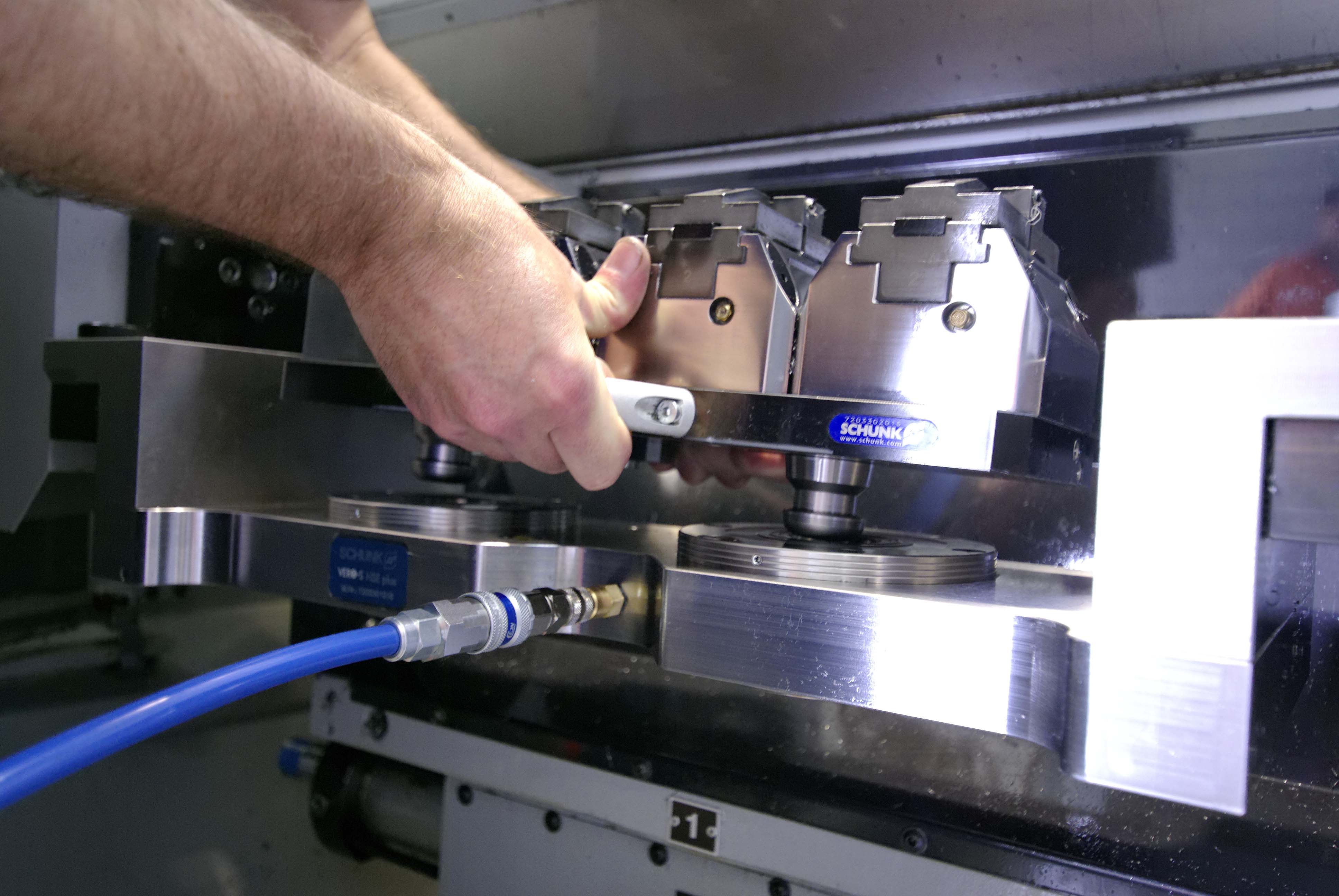
Schunk’s VERO-S workholding system can be loaded into a machine in seconds and offers repeatability within 0.0002". Image courtesy of Schunk.
Pieces of the Puzzle
Jeff Estes, director of Partners in THINC Technology Centers for Okuma America Corp., Charlotte, N.C., said numerous technologies are needed for machining-related rapid prototyping, including quick-change tooling and workholding, smart software systems and offline tool presetting, as well as a flexible machine tool and CNC.
“You have to look at all the pieces,” he said. “It’s about doing whatever you can to save time.”
Some shops use 5-axis mills or multifunction lathes to achieve that. Estes noted, however, that shops with even basic equipment can take several easy steps to improve throughput. One is cataloging cutting tools into groupings able to perform various types of work. “When you’re making one of this or three of that, you can’t afford tool changeovers,” Estes said. “You want to find the commonalities among all the tools resident in your turrets or carousels, standardizing wherever possible and organizing the work for your machines based on what kind of tools they carry. This helps minimize those that need changing.”
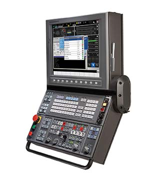
Conversational controls make machine operation more efficient while reducing setup times, both of which are important factors for anyone doing prototype work. Image courtesy of Okuma America.
Estes added that this grouping comes naturally to machinists, who mentally keep track of what tools are in which lathe or machining center and set up jobs accordingly. The key is documenting what’s in everyone’s head, collecting tool types, drawings and dimensions, and then placing all this information into a central location for everyone to see. This documentation is especially important as older generations of machinists retire and new employees take their place.
In some cases, standardizing the tool set means using a cutting tool that is less than optimal. This is a big no-no in a production environment, but it certainly reduces setup time when prototyping. “If it takes you 10 minutes to change a tool and set the offset, who cares if it takes 30 seconds longer to machine the part using the existing tool?” Estes asked. “You’re saving 9½ minutes of changeover during the setup. That’s what people need to think about.”
Push the Button
Workholding is something else to think about. “For job shops and production manufacturers alike, rapid prototyping requires the ability to load a workholding device in the machine without having to probe its position or set a work offset, and have confidence it will be within two-tenths (0.0002") of where it was the last time you used it,” said Brad Evans, workholding product manager at Schunk Inc., Morrisville, N.C. “You should be able to drop a fixture, vise or rotary table on the machine and hit ‘cycle start.’ ”
Many shops without a quick-change capability toe-clamp their indexers or 6" machinist’s vises on the machine table, leaving them there indefinitely. They know moving them is not worth the hassle. Leaving them in place, however, not only consumes valuable working space, it also reduces flexibility. Then when these shops have to change over, several hours are lost in the process.
Evans suggests modular workholding as an alternative, one where quick-change receivers are bolted to the table, dialed in one time, and then used as datum points for whatever pallets, vises or workholding fixtures are required.
Worried about the cost? Don’t be. Reducing downtime by even a few hours a week brings a quick return on workholding investment—often measured in months—and provides opportunities that didn’t exist previously. “I recently worked with a shop in Wisconsin that implemented our VERO-S system,” Evans said. “His best customer called with a rush order for a part he needed that same day. Normally, this order would have been a problem, but because the shop could change over in a few minutes, they were able to break into an existing setup and run the job in a few hours. By the time the driver left with the new part, the shop was back making chips on the previous job. The customer was happy, the shop received a nice premium for the rush order and did it without disrupting the production schedule.”
Get Modular
Along with toolholding, modularity offers the flexibility shops need if they’re to compete in the rapid-prototyping realm.
“Success with rapid prototyping benefits from modularity,” said Tom Raun, milling product manager at Iscar Metals Inc., Arlington, Texas. “The first thing that comes to mind is the toolholder, where quick-change adapters have long offered big setup-time savings. But there’s also the cutting tool itself to consider. The ability to customize the tool in terms of reach, type of application and type of shank is a huge benefit for rapid prototyping."
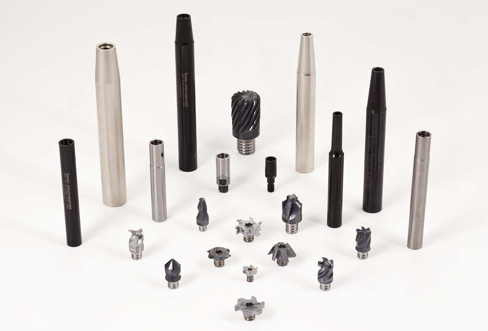
ISCAR’s Multi-Master system is modular in nature, making it easy to switch cutting tools as needed for various machining conditions. Image courtesy of Iscar Metals.
Examples include the need to quickly switch from a longer tool to one that’s shorter and load a tool with a reduced shank diameter to clear a vertical wall, he added.
Shops specializing in one-off and low-volume work never know from one day to the next what customers are going to order. Because of this, Raun recommends a cutting tool system like Iscar’s Multi-Master, which offers more than 40,000 combinations on a single platform. This allows manufacturers to quickly change to a variety of heads that encompass all types of milling applications. The heads are made of carbide or steel and can be used on steel, carbide or heavy-metal shanks. Repeatability should be better than ±0.0004" (0.0102mm).
“The Multi-Master system uses a screw-on head,” he said, “which allows tool replacement in seconds, even in tight quarters or where tools are difficult to reach—on Swiss-style lathes, for example, or a 90° head on a machining center. The time savings and convenience can have a huge impact on productivity, especially with prototype work, where every minute counts.”
Go Offline
Dr. Gregg Bigleman is the tool management solutions (TMS) manager at Zoller Inc., Ann Arbor, Mich. He said operational organization, which is crucial to quick turnaround and profitable prototyping, starts with a centralized database of tool information. The company offers such a database, separately or as part of its offline tool setting and measurement systems. According to Bigleman, Zoller’s database eliminates the silos of information common in many shops.
“Everyone ends up with their own spreadsheets or individual software systems,” Bigleman said. “This results in duplication of data and increases the chances for error. It also means that, when an order comes in, the person responsible for preparing the job has to walk out on the shop floor to see what inventory is available. He’ll check with the toolcrib and, perhaps, the machine operators to see if they have the gages, toolholders, inserts and fixtures needed to run the part, and then he can start developing the process. All these steps take a lot of time—something you especially can’t afford with prototype or low-quantity work.”
Having one database for tool and machining information is like conducting an orchestra where everyone’s playing from the same sheet of music, Bigleman said. Better yet, it provides an easy way to connect with external systems such as MachiningCloud (an independent aggregator of cutting tool data), speeds access to tool data and increases programming efficiency.
Those concerned about the effort needed for a plant-wide TMS implementation needn’t fear. “Zoller TMS is modular,” he said. “You can start small and add to it as needed. You never lose what you build on. The database—which is the same one the presetter uses—can also be used for cutting tool inventory, for fixture and gage management, and for the shop floor itself. You can see what jobs and tooling are in the machines. We also have a module for production planning. TMS allows you to minimize changeover time and make the most efficient use of resources.”
Redefining Throughput
The CAM system is another important element to increase prototype throughput. Don Davies, vice president of Americas for Camarillo, Calif.-based DP Technology Corp., the makers of ESPRIT CAM software, agreed that setup-time reduction is an important first step for any prototyping shop. He noted, however, the activities that take place prior to machine setup are just as important.
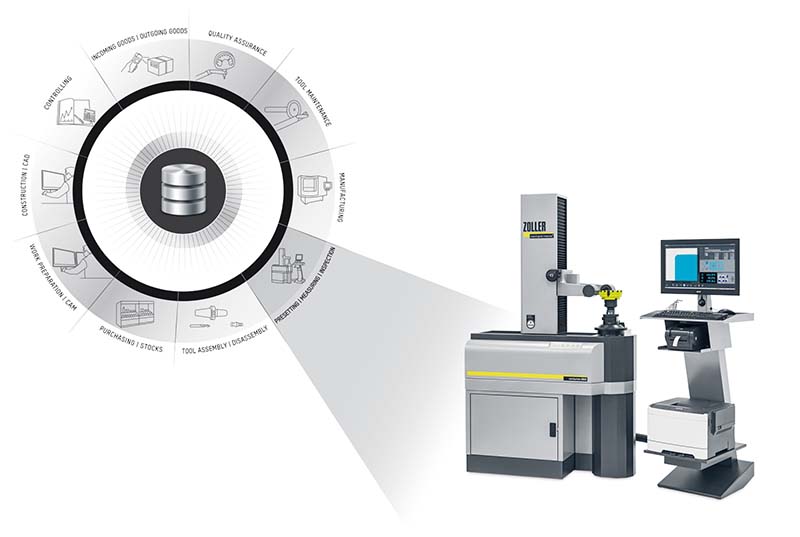
With Zoller's tool management solutions, all stations of the manufacturing process are linked via one central database: CAD/CAM, warehouse, purchasing, machines and the company’s presetters and vending equipment. Image courtesy of Zoller.
“One of the first things that has to be done on any job is verifying how it will fit in the machine tool,” Davies said. “That means pulling all the cutting tools, fixtures, clamps, chucks, vises—everything needed to machine a part—into a virtual environment and checking to see how they function. The more complex the machine, the more valuable this exercise becomes, but it’s a necessary step for any shop looking to increase efficiency on the shop floor.”
The CAM system is an important part of the equation, Davies said, but users also need the digital data to support this virtualization, something manufacturers and their suppliers have traditionally struggled with. That’s beginning to change as more companies embrace 3D modeling of their wares. Shops can view the machining process in a virtual world before pushing any buttons in the physical one.
One final consideration is automation. This doesn’t mean robotics and pallet changers, although these certainly have their place in some prototyping shops, but, rather, software automation. To Davies, software automation provides the ability to write specialized routines and macros that help eliminate much of the manual effort behind toolpath programming and simplify the “art to part” process.
“Some CAM systems provide an application programming interface, or API, that allow you to develop customized functionality,” he said.
Davies offered an example of a manufacturer in Minnesota that has automated roughly 80 percent of its toolpath generation using the APIs available in the ESPRIT system. Upon receiving an order, a clerk enters various part criteria, whereupon the system generates the machine code and decides what tools are needed to run the job.
“If I were to start a machine shop today, I’d hire people with the skills needed to understand manufacturing—speeds, feeds, tooling and what not—but also make sure they have knowledge of software programming,” Davies said. “That’s where our industry is headed.”
Contact Details
Contact Details
Contact Details
Contact Details

Contact Details
Related Glossary Terms
- arbor
arbor
Shaft used for rotary support in machining applications. In grinding, the spindle for mounting the wheel; in milling and other cutting operations, the shaft for mounting the cutter.
- centers
centers
Cone-shaped pins that support a workpiece by one or two ends during machining. The centers fit into holes drilled in the workpiece ends. Centers that turn with the workpiece are called “live” centers; those that do not are called “dead” centers.
- computer numerical control ( CNC)
computer numerical control ( CNC)
Microprocessor-based controller dedicated to a machine tool that permits the creation or modification of parts. Programmed numerical control activates the machine’s servos and spindle drives and controls the various machining operations. See DNC, direct numerical control; NC, numerical control.
- computer-aided manufacturing ( CAM)
computer-aided manufacturing ( CAM)
Use of computers to control machining and manufacturing processes.
- fixture
fixture
Device, often made in-house, that holds a specific workpiece. See jig; modular fixturing.
- gang cutting ( milling)
gang cutting ( milling)
Machining with several cutters mounted on a single arbor, generally for simultaneous cutting.
- lathe
lathe
Turning machine capable of sawing, milling, grinding, gear-cutting, drilling, reaming, boring, threading, facing, chamfering, grooving, knurling, spinning, parting, necking, taper-cutting, and cam- and eccentric-cutting, as well as step- and straight-turning. Comes in a variety of forms, ranging from manual to semiautomatic to fully automatic, with major types being engine lathes, turning and contouring lathes, turret lathes and numerical-control lathes. The engine lathe consists of a headstock and spindle, tailstock, bed, carriage (complete with apron) and cross slides. Features include gear- (speed) and feed-selector levers, toolpost, compound rest, lead screw and reversing lead screw, threading dial and rapid-traverse lever. Special lathe types include through-the-spindle, camshaft and crankshaft, brake drum and rotor, spinning and gun-barrel machines. Toolroom and bench lathes are used for precision work; the former for tool-and-die work and similar tasks, the latter for small workpieces (instruments, watches), normally without a power feed. Models are typically designated according to their “swing,” or the largest-diameter workpiece that can be rotated; bed length, or the distance between centers; and horsepower generated. See turning machine.
- machining center
machining center
CNC machine tool capable of drilling, reaming, tapping, milling and boring. Normally comes with an automatic toolchanger. See automatic toolchanger.
- milling
milling
Machining operation in which metal or other material is removed by applying power to a rotating cutter. In vertical milling, the cutting tool is mounted vertically on the spindle. In horizontal milling, the cutting tool is mounted horizontally, either directly on the spindle or on an arbor. Horizontal milling is further broken down into conventional milling, where the cutter rotates opposite the direction of feed, or “up” into the workpiece; and climb milling, where the cutter rotates in the direction of feed, or “down” into the workpiece. Milling operations include plane or surface milling, endmilling, facemilling, angle milling, form milling and profiling.
- robotics
robotics
Discipline involving self-actuating and self-operating devices. Robots frequently imitate human capabilities, including the ability to manipulate physical objects while evaluating and reacting appropriately to various stimuli. See industrial robot; robot.
- shank
shank
Main body of a tool; the portion of a drill or similar end-held tool that fits into a collet, chuck or similar mounting device.
- toolholder
toolholder
Secures a cutting tool during a machining operation. Basic types include block, cartridge, chuck, collet, fixed, modular, quick-change and rotating.
- toolpath( cutter path)
toolpath( cutter path)
2-D or 3-D path generated by program code or a CAM system and followed by tool when machining a part.
Author

Kip Hanson is a contributing editor for Cutting Tool Engineering magazine. Contact him by phone at (520) 548-7328 or via e-mail at [email protected].
Contributors
DP Technology Corp.
(800) 627-8479
www.espritcam.com
Iscar Metals Inc.
(817) 258-3200
www.iscarmetals.com
Okuma America Corp.
(704) 588-7000
www.okuma.com
Schunk Inc.
(919) 572-2705
www.schunk.com
Zoller Inc.
(734) 332-4851
www.zoller-usa.com