Rake angles make or break facemilling

Author William Leventon
Published
January 18, 2022 - 05:00pm

When it comes to cutting angles, the rake can make or break your facemilling process. Rake angles impact key parameters, such as chip flow, metal removal rate and tool life. So rake angles need to be chosen with an eye to the requirements of each application.

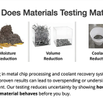
For cutters with indexable inserts, the rake angle is the inclination of an insert’s cutting face. There are two types of rake angles. The axial rake angle is the angle between the cutting edge and the axis of the cutter. This angle affects the facemilling process in several ways. It directs chip flow and impacts cutting-edge strength. In addition, toolmakers use the axial rake angle to control power consumption, said Nate Peters, senior tool design engineer at Greenleaf Corp. in Saegertown, Pennsylvania.

For cutters with indexable inserts, the rake angle is the inclination of an insert’s cutting face.
For cutters with indexable inserts, the rake angle is the inclination of an insert’s cutting face. A Cutting Tool Engineering image

“If you have a machine that doesn’t have a lot of horsepower,” he said, “we may change the axial rake to give you less cutting force so you’ll be able to use that machine in most circumstances.”

The other type of rake angle is the angle between the tooth face and cutter radius, measured in a plane perpendicular to the cutter axis. Known as the radial rake angle, this angle is important in determining cutting-edge sharpness and strength.

Rake angles also can be positive, zero or negative. A rake angle is positive when the sum of the tool’s wedge angle and the clearance angle between the insert and workpiece surfaces is less than 90 degrees. Positive rake angles make tools sharper and more pointed, which reduces their strength. Positive angles also lower cutting forces and power requirements.

When the sum of the tool’s clearance and wedge angles is exactly 90 degrees, the rake angle is zero. And it’s negative when the sum of those angles is greater than 90 degrees. Negative rake angles blunt tools and give them a stronger cutting edge than tools with positive rake angles. In addition, negative rake angles increase the cutting force and the power required for a cut. They also can increase friction, resulting in higher cutting temperatures, and improve surface finish.

Design Combos

Common cutter designs for facemilling use different combinations of positive and negative rake angles. As the name suggests, a double-negative milling cutter has a negative axial and negative radial rake angle. This arrangement makes a cutter very rigid and maximizes insert strength, said Bryan Stusak, national milling product manager at Iscar Metals Inc. in Arlington, Texas. Typically, he said, it also allows more inserts to be placed around the periphery of a cutter than other designs.

In addition, the double-negative design allows heavy feed rates and the most indexes because it accommodates double-sided inserts, said Josef Fellner, global product manager for indexable milling at Pittsburgh-based Kennametal Inc. He said this design is the best bet for shops looking for high metal removal rates and a good choice for facemilling ceramics, cast iron and high-temperature alloys.

 A facemill cuts with a negative axial rake angle.
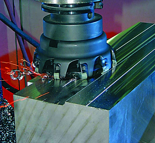
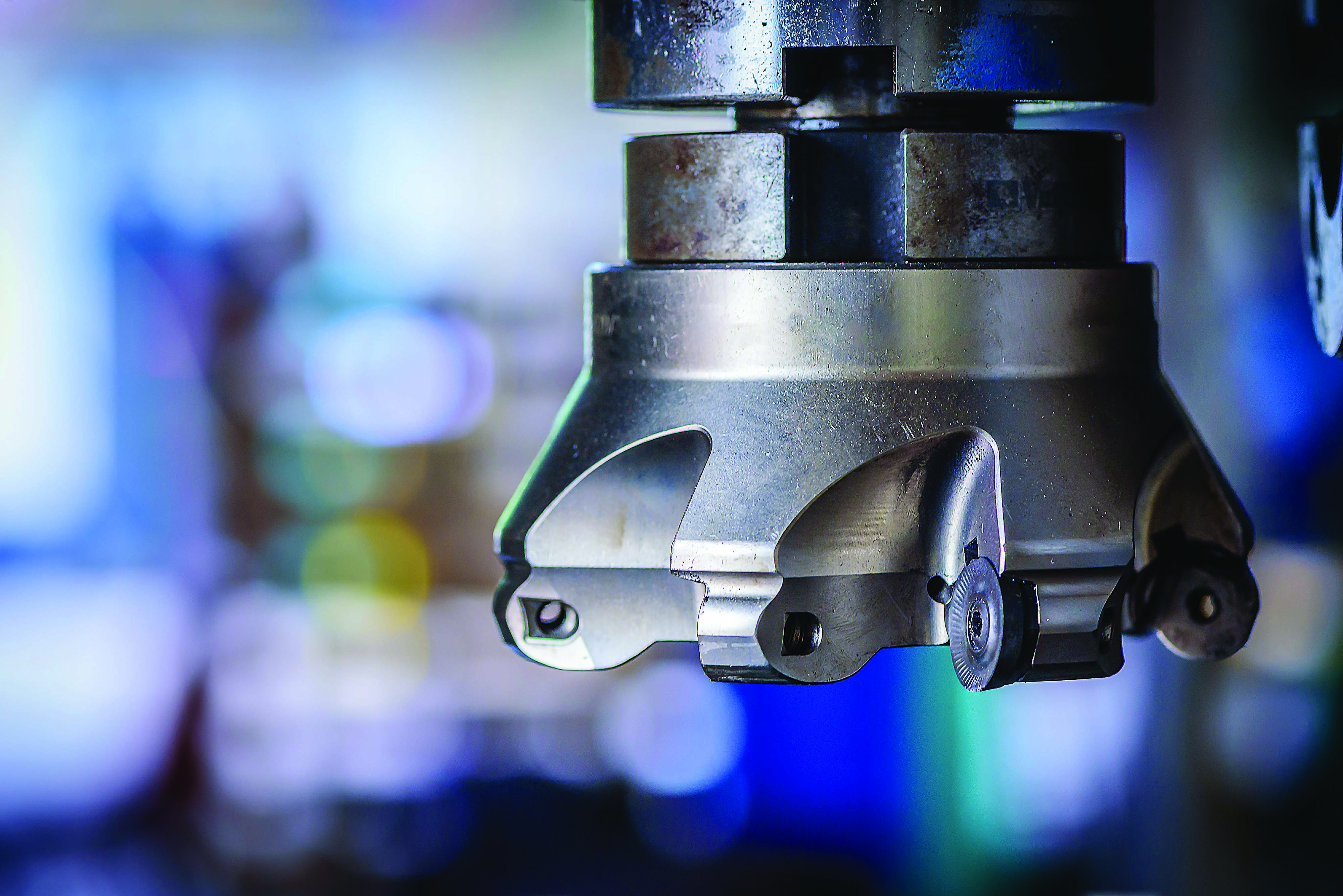
A facemill cuts with a negative axial rake angle. Image courtesy of Greenleaf

On the downside, Stusak pointed out that the double-negative design directs chips toward the workpiece and sometimes creates a burr. The design also subjects the workpiece, inserts and machine spindle to high cutting forces.

He believes that this rake angle configuration is better suited for older, more powerful machines with high metal removal rates than the machines commonly found at shops today.

“I don’t see the double negative very much anymore because it requires a lot of horsepower, and most machines now are lighter-duty machines,” Stusak said.

Another option for facemilling is a cutter with a double-positive design — that is, positive axial and radial rake angles. He said this arrangement allows freer cutting, which reduces cutting forces and lowers horsepower consumption. In addition, the double-positive design directs chips away from the workpiece.

On the other hand, Stusak said, double-positive inserts tend to be single-sided, and the cutting edges are weaker than their double-negative counterparts. He said double-positive cutters tend to pull on the workpiece and actually can lift it if it’s not fixtured properly.

Iscar Metals’ customers in the aerospace industry “use the double positive every day and twice on Sunday,” he said, adding that the double-positive design is the best for nonferrous and difficult-to-machine materials.

Peters recommends double-positive cutters for facemilling steel and aluminum alloys while Fellner said these cutters commonly are used for soft, gummy materials and lower-rigidity setups.

The third type of facemilling cutter is the positive-negative, or shear-milling, design, which features a positive axial rake and a negative radial rake orientation. Stusak said the positive-negative design produces lower cutting forces than the others, as well as freer cutting action. In addition, the design directs chips away from the workpiece, which helps with evacuation. The design works well with most materials.

Today, the positive-negative design is the choice for most face​milling cutters.

“If somebody wants a facemill, that is what we’re (usually) going to go with,” Peters said.

A major reason that the positive-negative configuration works for so many shops is its versatility.

“A lot of companies are looking for something that can cover them on everything — not just one material or one application,” Peters said. “If you’re looking for something (like that), we would suggest a positive negative.”

Also boosting the popularity of the positive-negative design is the fact that it allows the use of both double- and single-sided inserts. Since double-sided inserts can be flipped, as well as turned, they can offer twice as many cutting edges as single-sided inserts. For example, Fellner said Kennametal’s KSOM single-sided inserts have eight cutting edges while the company’s equivalent double-sided design has eight cutting edges per side for a total of 16.

When using a double-positive rake angle, the cutting edge of an insert needs to withstand larger forces. The edge requires a strong, stable design so it won’t break or wear too quickly.
When using a double-positive rake angle, the cutting edge of an insert needs to withstand larger forces. The edge requires a strong, stable design so it won’t break or wear too quickly. Image courtesy of Kennametal

“Most people are more concerned about cost per edge than anything, and double-sided inserts have a cost-per-edge advantage over single-sided inserts,” Stusak said.

Choosing Angles

In addition to the best rake angle combination for an application, the exact axial and radial rake angles themselves must be chosen. Normally, these decisions are left to the tooling supplier.

“I’ve had some customers that understand these concepts very well,” Stusak said. “They’ll say, ‘I want this particular design,’ and they understand why they want it. But 95% of them are not going to understand these details. So it’s really up to the tool manufacturer representative to specify what tool design is best for the application.”

Fellner said toolmakers base their choice of rake angles for a facemilling application on the following:

  • Workpiece material
  • Type of machining: light, medium roughing, heavy roughing or finishing
  • Available spindle horsepower
  • Stable or unstable fixture or workpiece
  • Tool reach
  • Small lot sizes or mass production
  • Performance criteria, such as cycle time and tool life

A rake angle is a function of both the shape of the insert and its orientation in the pocket. Once a
facemilling cutter is made, insert orientation cannot be changed. Fellner said, however, that shops can change a cutter’s rake angles to meet the requirements of different jobs by changing the shape of the inserts being used.

“You load different inserts with different geometries into the same cutter body,” he said.

Kennametal, for example, offers inserts with different geometries for general-purpose machining, light machining and heavy roughing.

Sometimes, the process of determining the best rake angles for an application requires trade-offs between properties.

“If customers say they need to make sure they’re not getting any chip wash across the face of their part, we’re going to go positive to try to get those chips away,” Peters said. “But we’re going to be upfront with them and tell them they’re going to get those chips away, but they’re giving up a little strength at the cutting edge, which means they may not get that same tool life that they’re looking for.”

He said Greenleaf’s engineers consider different options to come up with a rake angle combination that gives the customer the best possible combination of properties.

“We’re going to try our best to make sure we’re right in that sweet spot (where) we’re not necessarily giving up on cutting-edge strength, but we’re also not throwing all the chips into the face of the part.” 

Related Glossary Terms

  • alloys

    alloys

    Substances having metallic properties and being composed of two or more chemical elements of which at least one is a metal.

  • aluminum alloys

    aluminum alloys

    Aluminum containing specified quantities of alloying elements added to obtain the necessary mechanical and physical properties. Aluminum alloys are divided into two categories: wrought compositions and casting compositions. Some compositions may contain up to 10 alloying elements, but only one or two are the main alloying elements, such as copper, manganese, silicon, magnesium, zinc or tin.

  • axial rake

    axial rake

    On angular tool flutes, the angle between the tooth face and the axial plane through the tool point.

  • burr

    burr

    Stringy portions of material formed on workpiece edges during machining. Often sharp. Can be removed with hand files, abrasive wheels or belts, wire wheels, abrasive-fiber brushes, waterjet equipment or other methods.

  • ceramics

    ceramics

    Cutting tool materials based on aluminum oxide and silicon nitride. Ceramic tools can withstand higher cutting speeds than cemented carbide tools when machining hardened steels, cast irons and high-temperature alloys.

  • clearance

    clearance

    Space provided behind a tool’s land or relief to prevent rubbing and subsequent premature deterioration of the tool. See land; relief.

  • cutting force

    cutting force

    Engagement of a tool’s cutting edge with a workpiece generates a cutting force. Such a cutting force combines tangential, feed and radial forces, which can be measured by a dynamometer. Of the three cutting force components, tangential force is the greatest. Tangential force generates torque and accounts for more than 95 percent of the machining power. See dynamometer.

  • facemill

    facemill

    Milling cutter for cutting flat surfaces.

  • facemilling

    facemilling

    Form of milling that produces a flat surface generally at right angles to the rotating axis of a cutter having teeth or inserts both on its periphery and on its end face.

  • feed

    feed

    Rate of change of position of the tool as a whole, relative to the workpiece while cutting.

  • fixture

    fixture

    Device, often made in-house, that holds a specific workpiece. See jig; modular fixturing.

  • gang cutting ( milling)

    gang cutting ( milling)

    Machining with several cutters mounted on a single arbor, generally for simultaneous cutting.

  • milling

    milling

    Machining operation in which metal or other material is removed by applying power to a rotating cutter. In vertical milling, the cutting tool is mounted vertically on the spindle. In horizontal milling, the cutting tool is mounted horizontally, either directly on the spindle or on an arbor. Horizontal milling is further broken down into conventional milling, where the cutter rotates opposite the direction of feed, or “up” into the workpiece; and climb milling, where the cutter rotates in the direction of feed, or “down” into the workpiece. Milling operations include plane or surface milling, endmilling, facemilling, angle milling, form milling and profiling.

  • milling cutter

    milling cutter

    Loosely, any milling tool. Horizontal cutters take the form of plain milling cutters, plain spiral-tooth cutters, helical cutters, side-milling cutters, staggered-tooth side-milling cutters, facemilling cutters, angular cutters, double-angle cutters, convex and concave form-milling cutters, straddle-sprocket cutters, spur-gear cutters, corner-rounding cutters and slitting saws. Vertical cutters use shank-mounted cutting tools, including endmills, T-slot cutters, Woodruff keyseat cutters and dovetail cutters; these may also be used on horizontal mills. See milling.

  • radial rake

    radial rake

    Also known as the tool back rake, the angle between the tooth face and the radial plane through the tool point.

  • rake

    rake

    Angle of inclination between the face of the cutting tool and the workpiece. If the face of the tool lies in a plane through the axis of the workpiece, the tool is said to have a neutral, or zero, rake. If the inclination of the tool face makes the cutting edge more acute than when the rake angle is zero, the rake is positive. If the inclination of the tool face makes the cutting edge less acute or more blunt than when the rake angle is zero, the rake is negative.

Contributors

Greenleaf Corp.
814-763-2915
www.greenleafcorporation.com

Iscar Metals Inc.
817-258-3200
www.iscarmetals.com

Kennametal Inc.
800-446-7738
www.kennametal.com