Work produced by toolmakers and machinists reflects years of experience, training and difficult lessons. These people are a proud lot who are dedicated to the craft and work hard to demonstrate their skill. All have their own specialty and gravitate to a specific process, such as turning, milling or grinding, but achieving superior surface finishes is a common goal.
Producing a part with a silky smooth, bright appearance is regarded as a mark of expertise. This goal is accomplished in many ways, from adjusting cutting speeds and depths of cut to trying different geometries for cutting edges and strategically applying an emery cloth when nothing else works.
These actions are reinforced by quality control, customers and others who make appearance-based quality assessments. Evidence can be found in some of the old machinist sayings like “If you can’t make it right, then make it bright because they check the ugly ones first.” Appearance is important, but improper application of surface finish requirements can lead to lost productivity, increased costs and poor quality.
Design engineers must consider and balance the trade-offs among mechanical properties, how a part interacts in a system, appearance requirements and the cost of manufacture.
It is easy for machinists to become frustrated with stringent surface finish requirements, but surface finish is a critical component of part life. In general, a finer surface finish yields a stronger part than one with a rough surface finish. Research has demonstrated that failure modes like fatigue are exacerbated by rough surface finishes, so it is important for design engineers to specify a finish that will deliver the desired strength. Likewise, it is important for machinists to deliver the required finish to ensure that a part lasts as designed. This is one reason that aerospace manufacturers are sticklers about surface finish needs.
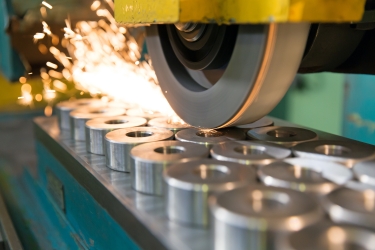
Producing a part with a silky smooth, bright appearance is regarded as a mark of expertise. Image: Cutting Tool Engineering
Processes like shot peening, a procedure that distributes small steel shot, or BBs, at high velocity, or roller burnishing, which passes a hard roller over a machined surface, can reduce the risk of fatigue cracking by imparting compressive stress into the surface of a part. Both practices are used extensively in the manufacture of turbomachinery components and provide a glassy, smooth finish.
Improper surface finishes also can cause other failures. Sealing surfaces for hydraulic actuators are a good example. Earlier in my career, I worked for an automotive company that manufactured power steering gears, which basically are specialized hydraulic cylinders. Keeping the 103 bar (1,500 psi) oil from leaking everywhere required having a 0.5 Ra — very slick, almost like a mirror — surface finish on the shaft so the seals would function properly. Any surface defect, including a poor surface finish, is a leak path and an opportunity for warranty claims. On more than one occasion, we had to quarantine and rework parts because a poor surface finish caused leaks upon assembly.
Although it may sound contradictory, striving for a great finish can produce a surface that is too smooth to function properly. Hydraulic seals require not only a smooth finish to prevent leaks — the seals also need enough surface irregularity to allow a film of oil to exist so they are lubricated properly, thereby avoiding premature wear.
Delivering the proper surface finish is important to ensure that a component is fit for service, as well as to improve productivity and costs.
Despite being a noble, skillful act, trying to deliver a surface finish that exceeds the requirement can reduce profitability. This is exactly what happens when a machinist spends time tweaking the setup to get a nice, shiny surface that is not required. Besides adding no value, time spent making adjustments is time that could be spent delivering completed parts. Getting the perfect finish almost always requires reducing the cutting speed, feed rate and depth of cut, all of which increase cycle times. Every shop owner, production manager and engineer knows that the first area to explore for cost savings is a cycle time reduction.
Working to deliver unnecessarily fine finishes also can result in spending money on tooling that is not needed. It is common for people to purchase an insert or a tool in the quest for the perfect finish, and local tool salespeople are happy to support an addiction to new tools. The acquisition cost of a new tool is only part of the cost as new tools often are placed on inventory lists and increase the cost of crib inventory.
More obvious is the cost of nonconformance. Parts with finishes that do not meet specifications frequently need to be corrected. Rework is never a value-adding activity and directly harms profit. In high-volume environments like automotive manufacturing, the cost of rework often exceeds the normal cost of manufacture because the rework is done outside the standard process.
We can’t always blame machinists for the cost of improper surface finishes. Engineers who ask for unnecessarily fine finishes are designing costs into parts that don’t add value. Likewise, parts with finish requirements that are not fit for service can result in premature or catastrophic failure. Specifying the proper finish is a balancing of mechanical requirements, production costs and process capabilities.
Complicating these situations are the myriad ways that surface finish requirements are communicated in specs and drawings. Ra, Rz, Rt and RMS are the most common. However, each of these has a different method of calculation, and results are not comparable. Machinists, engineers and programmers have lively debates about measurement techniques and often turn to the internet or a tool catalog looking for a magical conversion for resolution.
Surface finishes are as important as the dimensional characteristics of a part, and finish demands frequently are not given the same consideration as other needs in manufacturing. Failing to understand requirements can result in major cost issues. It is critical not only to deliver a finish to the specification but to challenge a designer when the specification appears to be too stringent. Researching and understanding the requirements, measurement techniques and mechanical aspects of surface finishes can reduce the risk of costly mistakes and improve the bottom line.
Related Glossary Terms
- burnishing
burnishing
Finishing method by means of compressing or cold-working the workpiece surface with carbide rollers called burnishing rolls or burnishers.
- cutting speed
cutting speed
Tangential velocity on the surface of the tool or workpiece at the cutting interface. The formula for cutting speed (sfm) is tool diameter 5 0.26 5 spindle speed (rpm). The formula for feed per tooth (fpt) is table feed (ipm)/number of flutes/spindle speed (rpm). The formula for spindle speed (rpm) is cutting speed (sfm) 5 3.82/tool diameter. The formula for table feed (ipm) is feed per tooth (ftp) 5 number of tool flutes 5 spindle speed (rpm).
- depth of cut
depth of cut
Distance between the bottom of the cut and the uncut surface of the workpiece, measured in a direction at right angles to the machined surface of the workpiece.
- fatigue
fatigue
Phenomenon leading to fracture under repeated or fluctuating stresses having a maximum value less than the tensile strength of the material. Fatigue fractures are progressive, beginning as minute cracks that grow under the action of the fluctuating stress.
- feed
feed
Rate of change of position of the tool as a whole, relative to the workpiece while cutting.
- gang cutting ( milling)
gang cutting ( milling)
Machining with several cutters mounted on a single arbor, generally for simultaneous cutting.
- grinding
grinding
Machining operation in which material is removed from the workpiece by a powered abrasive wheel, stone, belt, paste, sheet, compound, slurry, etc. Takes various forms: surface grinding (creates flat and/or squared surfaces); cylindrical grinding (for external cylindrical and tapered shapes, fillets, undercuts, etc.); centerless grinding; chamfering; thread and form grinding; tool and cutter grinding; offhand grinding; lapping and polishing (grinding with extremely fine grits to create ultrasmooth surfaces); honing; and disc grinding.
- mechanical properties
mechanical properties
Properties of a material that reveal its elastic and inelastic behavior when force is applied, thereby indicating its suitability for mechanical applications; for example, modulus of elasticity, tensile strength, elongation, hardness and fatigue limit.
- milling
milling
Machining operation in which metal or other material is removed by applying power to a rotating cutter. In vertical milling, the cutting tool is mounted vertically on the spindle. In horizontal milling, the cutting tool is mounted horizontally, either directly on the spindle or on an arbor. Horizontal milling is further broken down into conventional milling, where the cutter rotates opposite the direction of feed, or “up” into the workpiece; and climb milling, where the cutter rotates in the direction of feed, or “down” into the workpiece. Milling operations include plane or surface milling, endmilling, facemilling, angle milling, form milling and profiling.
- peening
peening
Mechanical working of a metal by hammer blows or shot impingement.
- quality assurance ( quality control)
quality assurance ( quality control)
Terms denoting a formal program for monitoring product quality. The denotations are the same, but QC typically connotes a more traditional postmachining inspection system, while QA implies a more comprehensive approach, with emphasis on “total quality,” broad quality principles, statistical process control and other statistical methods.
- shot peening
shot peening
Cold working a metal’s surface by metal-shot impingement.
- turning
turning
Workpiece is held in a chuck, mounted on a face plate or secured between centers and rotated while a cutting tool, normally a single-point tool, is fed into it along its periphery or across its end or face. Takes the form of straight turning (cutting along the periphery of the workpiece); taper turning (creating a taper); step turning (turning different-size diameters on the same work); chamfering (beveling an edge or shoulder); facing (cutting on an end); turning threads (usually external but can be internal); roughing (high-volume metal removal); and finishing (final light cuts). Performed on lathes, turning centers, chucking machines, automatic screw machines and similar machines.
Author

Christopher Tate is the owner of Tate Engineering, a Natchez, Mississippi, firm that helps manufacturers solve efficiency problems. Tate, who earned master's degree in industrial technology from Mississippi State University, has 32 years of experience in the metalworking industry.
