One of the helpful trends for users of manufacturing technology is that the various companies that constitute a machining system are partnering more frequently on research and development. As a CAD/CAM software developer with an in-house manufacturing lab, we’ve been immersed in this partnership concept for decades. To best develop our toolpaths and post-processors, we must know the capabilities and nuances of hundreds of CNC machine tool brands and models. To populate our cutting tool libraries and advise on ideal speeds and feeds, we likewise need to know the intricacies of myriad cutting tools available to end users. This knowledge comes from cooperation, communication and camaraderie among the numerous applications engineers at different companies involved in machining systems. These engineers work to help manufacturers more efficiently make superb parts.
It may sound easy, but the reality is much more challenging, from aligning schedules to competing with other priorities. It takes drive by individuals to see through a joint R&D project. When there is commitment, however, the synergy among entities can be like magic. Better-than-expected results can occur that are repeatable on a shop floor.
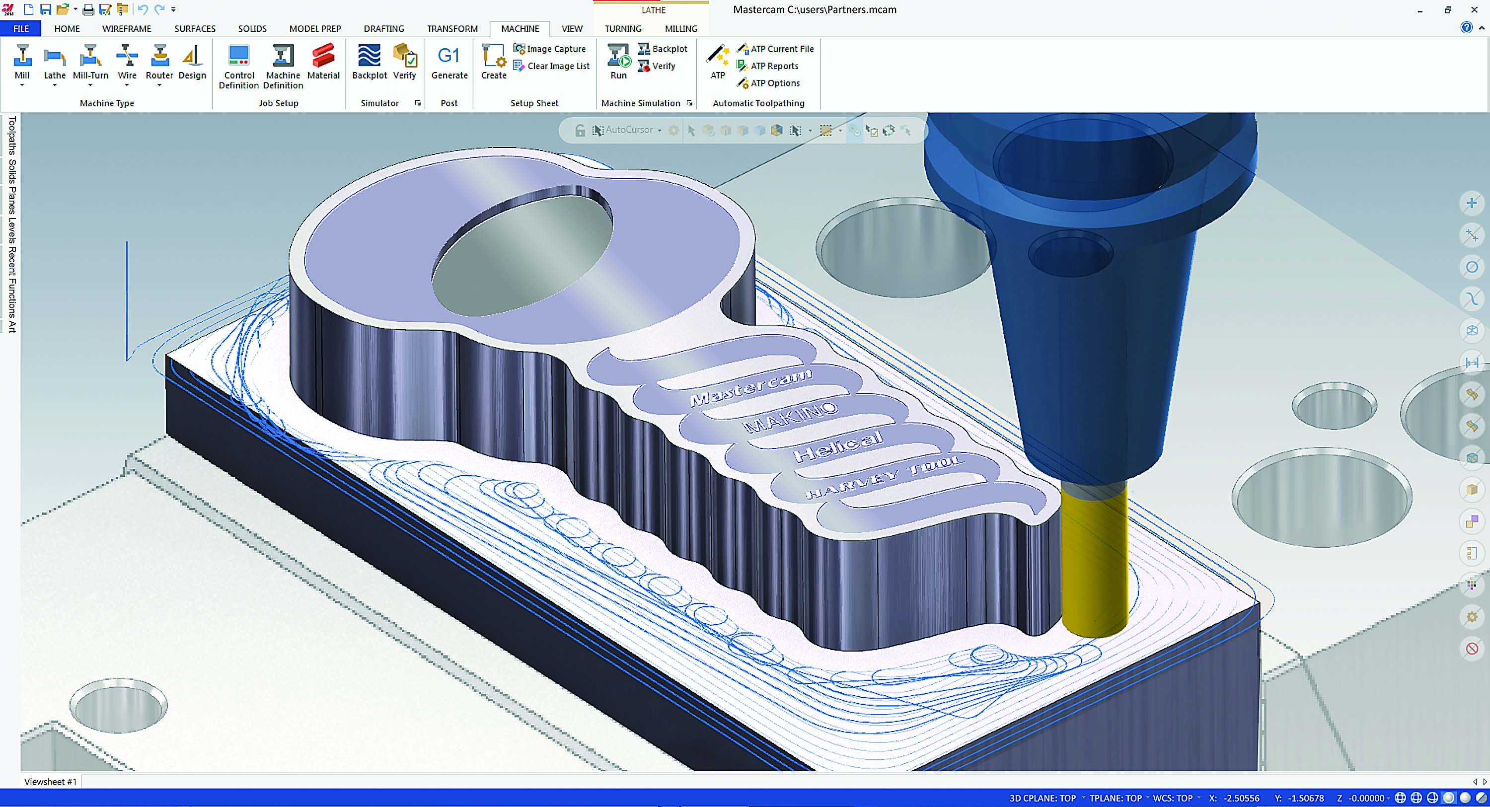
Mastercam’s Dynamic Motion roughing toolpaths contributed to ambitious material removal in the demo part. Image courtesy of CNC Software
An example of a recent project was among CNC Software Inc. (the CAD/CAM software), Helical Solutions LLC (the cutting tool) and Makino Inc. (the machine tool). It all began when Helical Solutions sent an email introducing its high-efficiency six-flute endmill with a chipbreaker. Mike Fecteau, senior applications engineer at Makino’s mold and die facility in Auburn Hills, Michigan, received that message, was intrigued and wanted to test the endmill on a high-horsepower, general-purpose machine platform. He reached out to Don Grandt, national application engineer at Harvey Performance Co. LLC, which owns Helical Solutions. Grandt then contacted me, knowing that our Dynamic Motion toolpath would help get the most efficient speed results out of the tool.
Grandt’s goal from the start was to achieve a material removal rate of 655 cm³/min. (40 in.³/min.). That’s an aggressive aim with a 12.7 mm (0.5") endmill. In addition to programming, my role was to design a 4140 alloy steel workpiece that looked cool but also had to have “real” part features that would be common in a mold or die component. We didn’t want this demonstration to be in a tightly controlled environment with conditions that couldn’t be replicated on a shop floor. We wanted to show that when these three elements are combined — a dynamic toolpath, a high-efficiency cutter and a well-built machine — these are the results that users can expect.
After several emails back and forth as Fecteau ran tests in Michigan and tweaked horsepower, speeds and feeds, he actually could increase all those aspects. So we then had our demo and the research to share with peers and end users. The operations involved roughing, finishing, chamfering and engraving. Here were the results:
Roughing
- Tool: Helical Solutions 12.7 mm, 0.76 mm (0.03") radius, six-flute chipbreaker
- 10,695 rpm and 30.8 hp used
- 13,513 mm/min. (532 ipm)
- Axial depth of cut: 25.4 mm (1")
- Radial DOC: 1.905 mm (0.075")
- MRR = 655 cm³/min.
Finishing
- Same tool
- 9,173 rpm
- 2,100.6 mm/min. (82.7 ipm)
- Axial DOC: 25.4 mm
- Radial DOC: 0.203 mm (0.008")
Chamfering
- Tool: Helical Solutions high-performance chamfer mill
- 12,000 rpm
- 3,000 mm/min. (118 ipm)
- Axial DOC: 1 mm
Engraving
- Tool: Harvey Tool 0.381 mm (0.015") runner cutter
- 14,000 rpm
- 508 mm/min. (20 ipm)
- Axial DOC: 0.1 mm
As always with R&D projects, we each learn something that we can store in our own knowledge
center for future use and to pass on to end users. For me, partnering with experts Fecteau and Grandt, I was confident in all the aspects of this demo, especially with the aggressive goal for material removal. But anything can happen, so it was still a thrill to see all these high-quality elements coming through on the promise.
Fecteau and I were also very surprised by the results of the chamfering and the interesting flute geometry on the chamfer tool that Grandt had recommended. Using the right chamfer tool can give a bit of an efficiency edge in not only cycle time but overall part quality. I used to think that a chamfer was a chamfer — nothing too special. But chamfers are often one of the first things to be perceived on a given part, and an ugly chamfer can dictate the visual perception of quality of a machined component. So using a high-quality chamfer tool does make a difference as those results convey.
In addition to our companies learning the technical aspects of this application and this combination of products for end users, there’s a tremendous benefit for all three of our companies’ customer bases. Our three companies have solid relationships with each other and quickly can diagnose and resolve issues in the field. We now have a hotline with each other, so to speak. If someone running a Makino machine has a Mastercam toolpath problem, Fecteau calls me. If I have a customer trying out the new six-flute tool and there’s a glitch somewhere, I call Grandt. No one points a finger at another party and makes a customer turn elsewhere for help. We try to troubleshoot among ourselves and fix things with very little hassle for customers.
Several entities may make up the fully automated systems being installed increasingly at shops large and small, so partnering and teamwork certainly are increasing. That’s good news for our industry — for both the technological evolution happening now and the expanding human connections that drive its progress.
For more information about the demo from this article, view a video presentation at www.ctemag.com entering this URL on your web browser: cteplus.delivr.com/2cuma
Contact Details
Contact Details
Contact Details
Related Glossary Terms
- chamfering
chamfering
Machining a bevel on a workpiece or tool; improves a tool’s entrance into the cut.
- chipbreaker
chipbreaker
Groove or other tool geometry that breaks chips into small fragments as they come off the workpiece. Designed to prevent chips from becoming so long that they are difficult to control, catch in turning parts and cause safety problems.
- computer numerical control ( CNC)
computer numerical control ( CNC)
Microprocessor-based controller dedicated to a machine tool that permits the creation or modification of parts. Programmed numerical control activates the machine’s servos and spindle drives and controls the various machining operations. See DNC, direct numerical control; NC, numerical control.
- endmill
endmill
Milling cutter held by its shank that cuts on its periphery and, if so configured, on its free end. Takes a variety of shapes (single- and double-end, roughing, ballnose and cup-end) and sizes (stub, medium, long and extra-long). Also comes with differing numbers of flutes.
- milling machine ( mill)
milling machine ( mill)
Runs endmills and arbor-mounted milling cutters. Features include a head with a spindle that drives the cutters; a column, knee and table that provide motion in the three Cartesian axes; and a base that supports the components and houses the cutting-fluid pump and reservoir. The work is mounted on the table and fed into the rotating cutter or endmill to accomplish the milling steps; vertical milling machines also feed endmills into the work by means of a spindle-mounted quill. Models range from small manual machines to big bed-type and duplex mills. All take one of three basic forms: vertical, horizontal or convertible horizontal/vertical. Vertical machines may be knee-type (the table is mounted on a knee that can be elevated) or bed-type (the table is securely supported and only moves horizontally). In general, horizontal machines are bigger and more powerful, while vertical machines are lighter but more versatile and easier to set up and operate.
- toolpath( cutter path)
toolpath( cutter path)
2-D or 3-D path generated by program code or a CAM system and followed by tool when machining a part.
- web
web
On a rotating tool, the portion of the tool body that joins the lands. Web is thicker at the shank end, relative to the point end, providing maximum torsional strength.
Author

Jesse Trinque is applications engineer at CNC Software Inc. in Tolland, Connecticut. For more information, call 860-875-5006 or visit www.mastercam.com.
