In this article, I’ll show a method to make a modular fixture for mill applications. The fixture uses an off-the-shelf mechanical clamp and a novel work stop.
Holding parts for machining on a milling machine can be challenging. For our purposes here, the problem is machining a long, skinny part. It is a tool steel machine knife that must have an array of countersunk holes installed. The part has dimensions of 4.75 mm by 19.05 mm by 469.9 mm (0.187"×0.75"×18.5"). Marks on the edges of the part are not allowed. The batch has 50 parts to process, so quick part change is in order. Figure 1 shows the fixture and the part unmounted. Figure 2 shows the part mounted on the fixture. Figure 3 shows details of the fixture hardware.
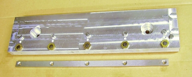
Figure 1: Shown are the fixture and the part unmounted. Image courtesy B. Taylor
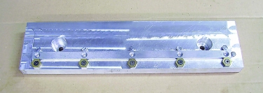
Figure 2: The part is mounted on the fixture. Image courtesy B. Taylor
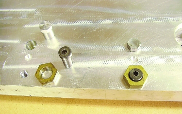
Figure 3: Details of the fixture hardware are displayed. Image courtey of B. Taylor
The fixture base is 38.1 mm by 127 mm (1.5"×5") aluminum bar stock that is 533.4 mm (21") long. The top and bottom faces of the bar stock are finished flat and parallel. The bottom face has two T-slot keys installed that fit into a T-slot on the milling machine table. Two counterbored holes are provided on the top face of the fixture to accept T-slot clamping nuts. One of the counterbores is finished with a boring bar so that hole can be used as an index when installing the fixture on the machine. The two T-slot keys and two T-slot clamping nuts all use the same T-slot on the milling machine table.
The fixture uses an array of five hex head pins and five edge clamps to hold the part being machined. One round dowel pin at the end of the part sets the length dimension. The hex pins are made from 12.7 mm (0.5") steel hex stock turned to 12.7 mm/12.675 mm (0.5"/0.499") dia. on one end. They fit into 12.725 mm (0.501") dia. reamed holes on the fixture. (See Figure 3.) The hex head pins are free to turn in the holes. This ensures that the part is clamped squarely against a hex face and there is an adequate clamping surface against the part. Using this method, marks are not made on the part edge. If round dowels were used, they would make a mess of the knife edge.
The clamps are fixture clamps by Mitee-Bite Products LLC in Center Ossipee, New Hampshire. These clamps have a brass nut mounted on a steel threaded bolt and are available in a variety of sizes. In this application, the size with 3/8"-16 thread is used. The clamps have an eccentric arrangement, so when the bolt is turned with a hex wrench, the nut moves radially on the bolt, clamping or unclamping the part. They are quick and easy to use.
This type of fixture using edge clamps and hex head pins has the advantage of positively locating horizontal dimensions. This way also can be used to clamp round or irregularly shaped parts with accuracy and repeatability. For a round part, using four clamping points works well. Use two hex pins to set X and Y position and two edge clamps to push the part against the hex pins. One hex pin at 0° and another at 90° and one edge clamp at 180° and another at 270° will do it. I hope that this helps.
Related Glossary Terms
- boring
boring
Enlarging a hole that already has been drilled or cored. Generally, it is an operation of truing the previously drilled hole with a single-point, lathe-type tool. Boring is essentially internal turning, in that usually a single-point cutting tool forms the internal shape. Some tools are available with two cutting edges to balance cutting forces.
- boring bar
boring bar
Essentially a cantilever beam that holds one or more cutting tools in position during a boring operation. Can be held stationary and moved axially while the workpiece revolves around it, or revolved and moved axially while the workpiece is held stationary, or a combination of these actions. Installed on milling, drilling and boring machines, as well as lathes and machining centers.
- fixture
fixture
Device, often made in-house, that holds a specific workpiece. See jig; modular fixturing.
- flat ( screw flat)
flat ( screw flat)
Flat surface machined into the shank of a cutting tool for enhanced holding of the tool.
- gang cutting ( milling)
gang cutting ( milling)
Machining with several cutters mounted on a single arbor, generally for simultaneous cutting.
- milling
milling
Machining operation in which metal or other material is removed by applying power to a rotating cutter. In vertical milling, the cutting tool is mounted vertically on the spindle. In horizontal milling, the cutting tool is mounted horizontally, either directly on the spindle or on an arbor. Horizontal milling is further broken down into conventional milling, where the cutter rotates opposite the direction of feed, or “up” into the workpiece; and climb milling, where the cutter rotates in the direction of feed, or “down” into the workpiece. Milling operations include plane or surface milling, endmilling, facemilling, angle milling, form milling and profiling.
- milling machine ( mill)
milling machine ( mill)
Runs endmills and arbor-mounted milling cutters. Features include a head with a spindle that drives the cutters; a column, knee and table that provide motion in the three Cartesian axes; and a base that supports the components and houses the cutting-fluid pump and reservoir. The work is mounted on the table and fed into the rotating cutter or endmill to accomplish the milling steps; vertical milling machines also feed endmills into the work by means of a spindle-mounted quill. Models range from small manual machines to big bed-type and duplex mills. All take one of three basic forms: vertical, horizontal or convertible horizontal/vertical. Vertical machines may be knee-type (the table is mounted on a knee that can be elevated) or bed-type (the table is securely supported and only moves horizontally). In general, horizontal machines are bigger and more powerful, while vertical machines are lighter but more versatile and easier to set up and operate.
- milling machine ( mill)2
milling machine ( mill)
Runs endmills and arbor-mounted milling cutters. Features include a head with a spindle that drives the cutters; a column, knee and table that provide motion in the three Cartesian axes; and a base that supports the components and houses the cutting-fluid pump and reservoir. The work is mounted on the table and fed into the rotating cutter or endmill to accomplish the milling steps; vertical milling machines also feed endmills into the work by means of a spindle-mounted quill. Models range from small manual machines to big bed-type and duplex mills. All take one of three basic forms: vertical, horizontal or convertible horizontal/vertical. Vertical machines may be knee-type (the table is mounted on a knee that can be elevated) or bed-type (the table is securely supported and only moves horizontally). In general, horizontal machines are bigger and more powerful, while vertical machines are lighter but more versatile and easier to set up and operate.
- parallel
parallel
Strip or block of precision-ground stock used to elevate a workpiece, while keeping it parallel to the worktable, to prevent cutter/table contact.
Author

Brandt Taylor is owner of Berlin, Massachusetts-based Taylor Engineering, a machine shop.