Today’s tools for computer-aided design for computer-aided manufacturing offer a wide variety of options that allow users to modify or enhance part geometry so toolpaths can drive machine tools to accurately and efficiently cut parts.
CAM-generated toolpaths on a CNC machine reflect the selected geometry from a CAD model. If a CAD model has issues, such as large gaps between surfaces or surface imperfections from reverse engineering, CAD tools can be used to improve those areas to create better parts. Mesh editing functionality is one of those tools.
The mesh tools in our CAM software are intended to help users improve cutting organic geometry provided by scanned data. When I accepted my current role at CNC Software LLC, we just had spent an entire year working on Mastercam CAD functions and creating several mesh-related improvements. Different from reverse engineering tools, these tools make meshes machinable. We decided to develop these new tools based on feedback from customers, including those who work at small shops. As a former reseller of CAD/CAM software, I have seen the issues that can arise with meshes, so I was happy we chose to improve them.
Clean Up Your Mesh
Many of our customers are small job shops that receive scanned mesh files or STL files. In the past, not much could be done with these files — and some companies charge a lot to convert mesh entities to surfaces. With mesh editing, users now can import, create, edit and refine mesh entities directly in their software and are not limited by what their customers provide as models, such as STL or 3MF. From filling holes and smoothing surfaces to modifying facets and refining mesh data, programmers and designers can work directly with the mesh to identify and resolve issues. This new CAD function offers the ability to smooth a mesh model and create a smoother toolpath for more precise machining and improved surface finish quality. Programmers can fix scan imperfections to create contiguous toolpath motion, reduce unnecessary details that enlarge file size, and make files suitable for toolpath creation.
Meshes always have presented challenges for machining, but with advances in reverse engineering, such challenges are becoming even more prevalent. To address these and other potential issues for machining, Check Mesh analyzes and fixes problem areas to prepare models for programming, allowing users to take advantage of other new mesh tools. The feature checks for folded facets and offers the option of deleting facets that contain errors. One particular challenge addressed by new CAD tools is rippled surface models that started as scans. Programmers can convert surfaces to a mesh, then isolate and smooth areas to achieve smooth cuts. It sounds simple, but smoothing the model surface makes a big difference in cutting techniques.
A customer recently tried to machine an intake runner for a car. The goal was to achieve a smooth finish, but the provided surface model contained ripples. Scanning an intake runner is tricky; reverse engineering a part into a surface model can be tedious. If splines are not aligned, ripples can form, twisting the surface. In this case, converting the surface to a mesh, then smoothing it, was the best strategy.
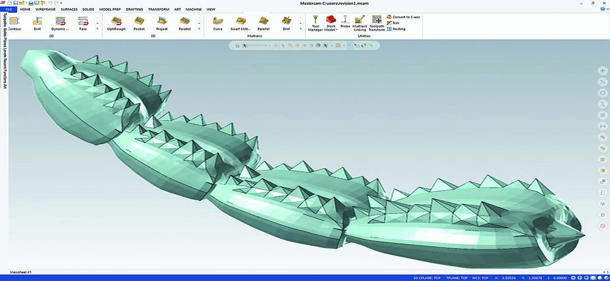
Instead of trying to resurface a part, the Meshes From Entities CAD tool enables conversion of a surface to a mesh. Applying the Smooth Area feature to the new mesh allows users to go in and pick an area by facets. The cursor, which looks like a small disc, then permits application of various smoothing tools — a user-friendly process similar to virtual coloring. Users can apply a toolpath directly on the mesh and surrounding surface or solid geometry. Smooth Area provides the option to select the entire mesh, or specific facets can be highlighted. Smoothing capabilities can yield a better-quality cutting area or a better-quality finish on the cut. If you have only a mesh model that has to be cut, it likely will come out faceted. The smoothing tool changes all that.
If you receive a mesh model that needs work in a specific section, keep in mind that it can be trimmed and cleaned. For a mesh that contains disjointed bodies, we have the ability to break it up into more manageable, single meshes. We also can offset a mesh to help clean up a mesh that was created from disjointed bodies or just make the mesh larger.

If a shop receives a solid without feature history, CAD model prep tools are a quick way of modifying a solid to help machinists create something in tolerance. Also, CAD tools today let us push and pull solid faces; features may be moved around without adding solid feature history to the model. The Push-Pull Direct Editing function permits simultaneous editing of multiple bodies simply by dragging geometries with a mouse or by entering a delta value. Users have the option to create a chamfer or fillet just by pushing on an edge.
Path of Least Resistance
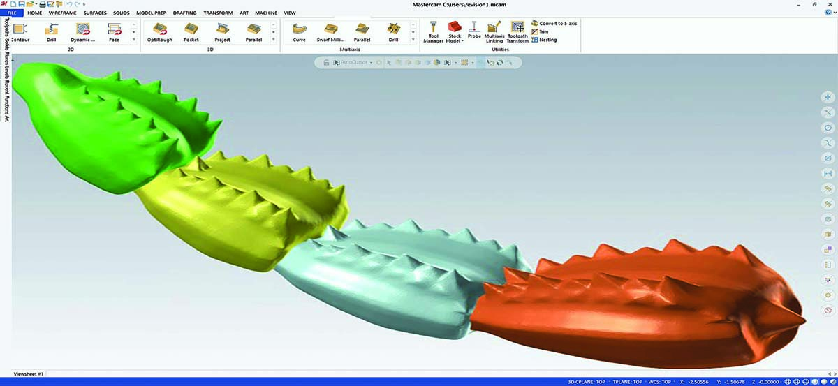
An important part of programming is readying a model for toolpaths. User-friendly CAD tools help simplify and expedite the process. For example, colors may be assigned to mesh entities, surfaces and faces. A programmer then can use the colors to quickly select toolpaths.
Another method of cleaning up a mesh is to use the Refine CAD tool. This improves the mesh model for finish machining by adding data points in detailed areas and reducing them in less detailed areas. Programmers control the size of facets and edges to ensure accuracy. The current host of available mesh tools can help create a better-quality surface or better-quality finish on the cut.
Sometimes a solid model may have edge tolerance issues. Solid tools to simplify or optimize the solid can yield improved results when applying toolpaths. If
something that cannot be seen with the naked eye is causing irregularities in toolpaths, running a Simplified solid, an Optimized solid or a Repair could result in more efficient toolpathing. Users simply click on the function and get a result. The software indicates if an issue was optimized. If users get odd results on a toolpath, running Optimize and reapplying the toolpath could improve the outcome.
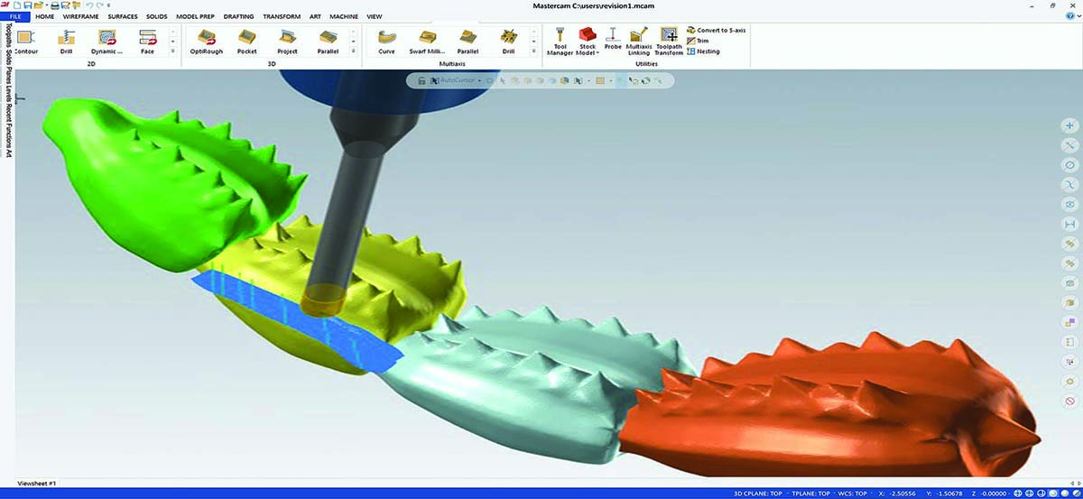
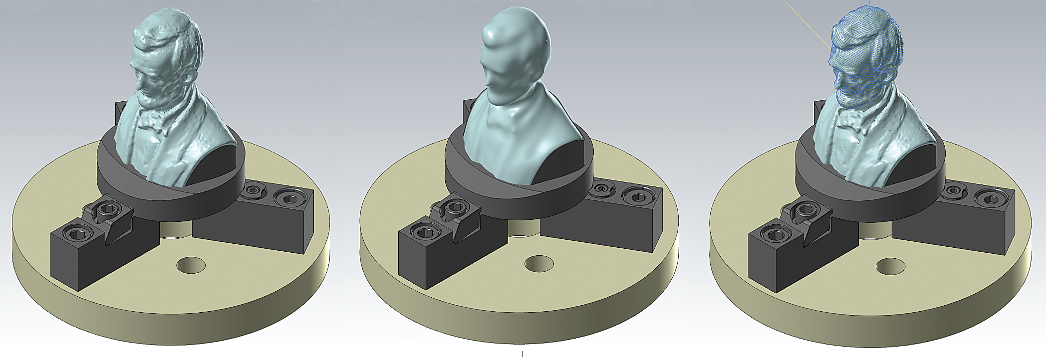
In addition to smoothing model-cutting regions for cleaner cuts, mesh tools can be used with a multi-axis toolpath for machining complex shapes. Trying to control motion and not have the tool flip around can be challenging. For a recent Mastercam training session, we created a five-axis toolpath on a model of a bust of Abraham Lincoln, an organic shape. Our engineers used a mesh model and smoothing tools to achieve optimum motion and better tool-axis control. Initially, due to the amount of design detail, the tool tended to flip around. By making a copy of the original mesh and then smoothing out the fine detail, the tool flowed better and still cut the bust. Tilting was not as unpredictable. Using the original mesh to drive the toolpath and using the smoothed mesh as tool-axis control allow the programmer to create an uninterrupted continuous-motion toolpath.
For multi-axis machining, the less axis movement there is on a multi-axis toolpath, the better. Less movement means a more rigid tool and a cleaner finish. Improving axis control and reducing flipping and tilting lead to reduced cycle times and improved part quality.
Our CAM software always has been able to apply toolpaths to mesh models. The difference now is we added more flexibility for dealing with mesh entities, giving more control over toolpaths to customers. Before, we did not have the ability to work with meshes to this extent.
More and more people are scanning things — mesh models can be created using cellphone technology. If you have an Apple iPhone, you can create a mesh and 3D-print it. It is amazing what is out there. We believed that companies needed more tools to aid working with the variety and quality of scans coming into shops. New CAD tools thankfully help programmers deal with every kind of scan. Job shops can accept models and not reject a job because it was a mesh.
Our CAD for CAM team makes software that enables CNC programmers to handle all types of CAD models. We want each programmer to have the proper tools to help prepare parts for machining.
Contact Details
Related Glossary Terms
- computer numerical control ( CNC)
computer numerical control ( CNC)
Microprocessor-based controller dedicated to a machine tool that permits the creation or modification of parts. Programmed numerical control activates the machine’s servos and spindle drives and controls the various machining operations. See DNC, direct numerical control; NC, numerical control.
- computer-aided design ( CAD)
computer-aided design ( CAD)
Product-design functions performed with the help of computers and special software.
- computer-aided design ( CAD)2
computer-aided design ( CAD)
Product-design functions performed with the help of computers and special software.
- computer-aided manufacturing ( CAM)
computer-aided manufacturing ( CAM)
Use of computers to control machining and manufacturing processes.
- computer-aided manufacturing ( CAM)2
computer-aided manufacturing ( CAM)
Use of computers to control machining and manufacturing processes.
- fillet
fillet
Rounded corner or arc that blends together two intersecting curves or lines. In three dimensions, a fillet surface is a transition surface that blends together two surfaces.
- solid model
solid model
3-D model created using “building blocks.” This is the most accurate way of representing real-world objects in CAD.
- surface model
surface model
3-D model defined by surfaces. The surface consists of polygons.
- tolerance
tolerance
Minimum and maximum amount a workpiece dimension is allowed to vary from a set standard and still be acceptable.
- toolpath( cutter path)
toolpath( cutter path)
2-D or 3-D path generated by program code or a CAM system and followed by tool when machining a part.
Author

Matt Kelly is product owner of the CAD design team at CNC Software LLC in Tolland, Connecticut. For more information, call 860-875-5006 or visit www.mastercam.com.
