Manufacturing process can help part design

Author Frank Burke
Published
September 03, 2020 - 10:00am

While the primary consideration of a part designer or design team is the functionality of a part, the manufacturing process and the end product can be improved significantly by taking into account various elements related to manufacturing, including machinability, tooling, assembly, desired finish and economy of production. This is especially true as parts become more complex, exotic materials become more common and CAD systems and other design protocols become more technologically advanced. New design tools, such as those based on artificial intelligence protocols, have added demands for decision-making to the overall process.

Another challenge can arise in situations in which the design function is entirely separate from manufacturing — for example, when job shops are requested to quote based on a CAD file from a manufacturer. In some cases, the part in question cannot be made based on the initial design. Different families of parts also can require completely different manufacturing strategies.

Design for Manufacturing

Fraser, Michigan-based Eifel Inc. knows these concerns well. It specializes in production and prototype tooling for automotive interiors, as well as advanced tooling for the medical and aerospace industries.

“We typically work with H13 and S7 steels for abrasive plastics,” said Richard Hecker, second-generation owner and CEO. “For more conventional plastic parts, we use a milder steel, such as P20. Our process typically starts when we get a 3D part design. After reviewing the design internally, we frequently consult with the customer on opportunities to reduce complexity and identify areas in which we could save money on the tooling. We also obtain background information on how the part will be used and the type of plastic that will be molded. We need to have a comprehensive understanding of the customer’s needs.”


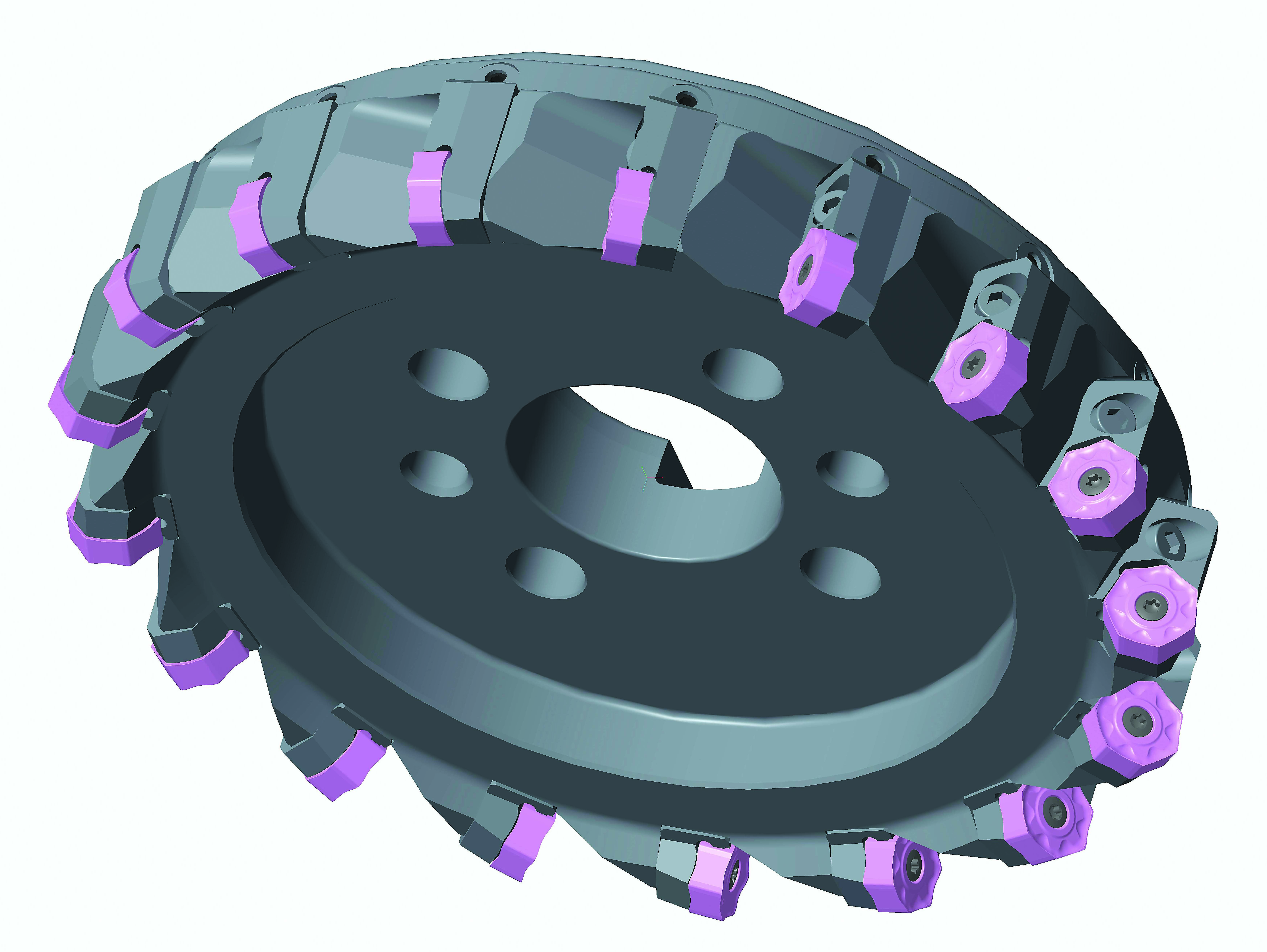
A 3D image (above) is displayed of a specially designed cutting tool.  Image courtesy Mitsubishi Materials U.S.A.

Designing for manufacturing often includes not only the design of a part but incorporation of part fixturing. Macro Tool & Machine Co. Inc. in LaGrangeville, New York, began as a local job shop in 1968. The company now services a nationwide customer base, including aircraft and military aerospace, medical implants and tools, sporting equipment and automotive applications.

“We work in a variety of metals, ranging from sheet metal to steels, aluminum and exotics and high-temperature steel alloys,” said CEO and President Daniel Siegel. “As a job shop, we are generally unable to ask for changes to part designs except occasionally for reduced tolerances or further specifications. For instance, customers sometimes give us CAD files without the tolerances for each hole, and that’s something we have to verify.”

The inability to change the design of customer parts has resulted in the development of fixturing that delivers precise repeatability and shortened changeover times. Knowing that such challenges were not unique to his company, he developed a line of pallet-type tooling systems, indexers, single and double vises, and pallet-mounted chucks marketed under the brand name STS, which stands for Siegel Tooling Systems. Created for small and midsize parts, the products aim to increase output while avoiding the high cost of customized fixturing.

The critical nature of the design function is most apparent in the development of specialized cutting tools.

“Special tools place a dual responsibility on the manufacturer,” said Engineering Manager Paul Ditosto of Mitsubishi Materials U.S.A. Corp. in Costa Mesa, California. “On the one hand, we have to be sure that the tool we design will perform its desired function for the customer. At the same time, we have to consider the most effective and economical means of producing it. This is further complicated by the ever-increasing number of carbide grades and specialized coatings, which have to be matched to achieve the optimum combination. To obtain the best results, we have to constantly keep in mind our customer’s manufacturing process, as well as our own. Although we can occasionally modify an off-the-shelf item, our prototype designs have to be extremely exact. And because our manufacturing facilities are located globally, the sequence of operations must be spelled out.”

It’s Complicated

The complex nature of many modern parts and the materials they are made from have expanded the considerations that come into play in designing for manufacturing. Machinability, finish, quality, tolerance, economy of production, eventual method of assembly and possible interface with other components of different materials are all elements to be taken into account.


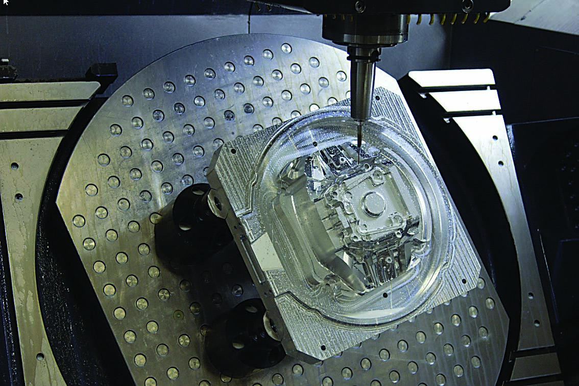
A mold for a steering wheel is machined using P20 steel.  Image courtesy of Eifel

“It’s essential that we understand what the customer is trying to do, and there are many questions that have to be asked,” Ditosto said. “These would include: Can we achieve the desired finish? Can we minimize the cycle time? What are they using now? And if this is a modification of an existing design, why do they want to alter the current design?”

Hecker also cites the necessity of extensive dialogue, not only with a customer but sometimes with its suppliers.

“We have to understand the importance of the part, as well as many of the elements of the molding process,” he said “For instance, in the automotive industry, air bag covers have to meet specifications for appearance and — even more important — for function. We must ascertain how the part can be molded, how the cooling process works and what temperature the part will be checked at. To answer those and other questions, we sometimes must talk with the customer’s supplier about the characteristics of the types of plastics that will be molded. It’s a matter of knowing both our business and our customer’s.”

Siegel mentioned the importance of tolerances and the sequencing of operations in defining a manufacturing strategy.

“We have to ask ourselves whether a part or component should be heat-treated first or after it’s produced,” he said. “Also, if bores are required, do we do that earlier or later? There are always a lot of questions, and answering them in advance eliminates misunderstandings.”

Tooling represents a significant factor for part designers. If a part can be generated with conventional tooling, costs can be substantially less than if special tooling is required.

“There are times when it’s impossible to avoid specialized tooling,” Siegel said, “and that has to be taken into account in calculating the cost of the job and the value of the part.”


A pallet is shown for a specific customer application. Macro Tool & Machine also dedicates vises and chucks on pallets to fill particular needs. Image courtesy of Macro Tool & Machine

Eifel emphasizes knowing the capabilities of CNCs, EDMs and tooling and how each injection mold fits into the machining process.

“Five-axis machining provides a great amount of flexibility,” Hecker said. “We want to use the shortest cutter possible in order to achieve the most precise results. We also use shrink-fit tooling to reduce deflection.”

Where’s the Software?

The demand for more software features related to manufacturability is being answered in the latest versions of several CAD/CAM/CAE packages. Ditosto and his team use a number of systems depending on the task, type of design and complexity.

“Based on the complexity of the design, we choose the appropriate design software,” he said. “We have a few options we tend to lead with, and it might be dependent on how close the design is to one of our standard tools. We would tend to stay with the design system which the standard product was developed with. On the CAE side, we have a couple of products we use depending (on) if it is a structure (design) or optimization (manufacturing) process. AutoCAD, Autodesk Inventor, Creo/Pro/E, Mastercam, Esprit, Solidworks CAM, Siemens NX, 3D Systems, hyperMill, Vericut and Production Module all have their place when it comes to CAD/CAM and CAE. CAM systems have really changed in the past 10 years. Visualization and simulation with many of these products is quite impressive. We partner with all of the above CAM software brands at our MTEC (Materials Technology and Education Center) in North Carolina to help solve manufacturing challenges. It’s amazing what these products can do, and we look forward to any new features that may be introduced down the road.”

Siegel sees the benefits of versatility in software selection.

“Although we’re aware of the newer softwares, we frequently work in 2D for the sake of simplicity,” he said. “One design that appeared at first to be simple but wasn’t was a bar of pure iron that needed to be plated. The tolerance was 0.0001" (0.0025 mm), and it was ultimately used for its magnetic properties.”

Software can enhance the process by providing valuable tools.

“We perform a draft analysis on the molds we produce in order to anticipate challenges before they occur in the machining process,” Hecker said. “The wrong draft angle on a cavity can cause scuffing. And if we discover that in the early stages of the process, we can determine whether to revise the tooling or the toolpath or go for more detail.”

The advent of such technologies, including generative design and 3D printing, as well as the demand for microparts capable of assembling themselves, continues to magnify the importance of incorporating manufacturability at the design stage. Likewise, the increasing array of options for materials and manufacturing techniques will heighten demand for analytics software and AI-based tools that can evaluate the choices inherent in part design, manufacturability, part performance, economy of production and — in an age of greater ecological awareness — predictable part life and recycling/disposal considerations.    


Related Glossary Terms

  • abrasive

    abrasive

    Substance used for grinding, honing, lapping, superfinishing and polishing. Examples include garnet, emery, corundum, silicon carbide, cubic boron nitride and diamond in various grit sizes.

  • alloys

    alloys

    Substances having metallic properties and being composed of two or more chemical elements of which at least one is a metal.

  • computer-aided design ( CAD)

    computer-aided design ( CAD)

    Product-design functions performed with the help of computers and special software.

  • computer-aided engineering ( CAE)

    computer-aided engineering ( CAE)

    Engineering functions performed with the help of computers and special software. Includes functions such as determining a material’s ability to withstand stresses.

  • computer-aided manufacturing ( CAM)

    computer-aided manufacturing ( CAM)

    Use of computers to control machining and manufacturing processes.

  • machinability

    machinability

    The relative ease of machining metals and alloys.

  • tolerance

    tolerance

    Minimum and maximum amount a workpiece dimension is allowed to vary from a set standard and still be acceptable.

  • toolpath( cutter path)

    toolpath( cutter path)

    2-D or 3-D path generated by program code or a CAM system and followed by tool when machining a part.

Author

Frank Burke has more than 35 years of experience in the machine tool and allied industries. He has worked for Cincinnati Milacron and subsequently for White-Sundstrand Machine Tool Corp. He has written extensively on technology and communications topics and holds an MBA from The Wharton School of the University of Pennsylvania. Telephone: (414) 225-9200. E-mail: frank.b@burkeandtowner.com.

Contributors 

Eifel Inc.
586-296-9640
www.eifel-inc.com

Macro Tool & Machine Co. Inc.
845-223-3824
www.macrotool.com

Mitsubishi Materials U.S.A. Corp.
800-523-0800
www.mmus.com