Since the 1980s, purchasers of CNC lathes, or turning centers, have had the option of including live tooling with their machines.
In a standard turning operation, the workpiece is turned against a static cutting tool. Live tooling, in contrast, moves. Live, or driven, tools are offered in straight and angled configurations and can be used for axial and radial cutting. Live tooling allows the user to mill, bore, drill, tap and perform operations other than turning.
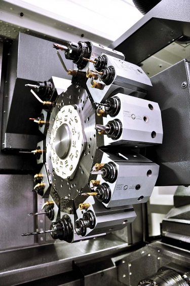
Koma Precision’s Alberti live-tooling systems benefit from improvements in gear
and bearing fabrication. Image courtesy of Koma Precision.
In a typical setup, the tools are mounted on a disc turret. With a face-mount version, the tools are located on the front of the tool-plate face; on a radial-mount or star turret, the tools are arrayed on the OD of the tool plate. A servo in the turret powers tool indexing and operation. Driven by the CNC, with a wide range of possible spindles, subspindles and toolholders, the live tools perform off-center operations while the workpiece remains oriented to the main spindle.
From the start, live tooling was added to increase a lathe’s usefulness. What many users of lathes and live tooling don’t realize is just how useful live tooling has become. State-of-the-art live tooling is versatile enough that it is applied even when the turning function of the lathe itself isn’t.
“There’s a lot of work being done these days that you can bar-feed through a lathe, maybe do a little turning—and maybe not even do any turning,” said Preben Hansen, president of live-tool maker Heimatec Inc., Prospect Heights, Ill. “We’ve got a medical customer up in Minnesota that doesn’t even turn the part, but they’re using lathes to finish it complete. It’s all live-tool work. The workpiece is [made from] a small bar, it’s expensive material, and they can feed it out, finish the whole thing, and cut it off and be done. There’s no secondary setups or wasted material, and the operation is basically unattended that way.”
Fewer Setups
Other industry experts agree that a live-tooling system offers significant advantages. Frank Cerrito, general manager of Koma Precision Inc., East Windsor, Conn., put it succinctly, “The main reason customers invest in live tooling is that it allows them to do an operation that would have otherwise required another setup, off of the lathe. So it saves time and prevents possible errors.” Koma Precision carries Alberti brand live tools.
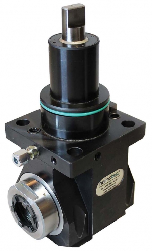
Heimatec's BMT 65 face-working tool adds versatility to what can be done on a lathe. Image courtesy of Heimatec.
Leigh Bickham, product manager for Sauter and EWS live-tool distributor ITI Tooling Co. Inc., Ramsey, N.J., noted: “If you’re working on the OD of a part and you then need to mill a flat or drill and tap a hole, you can’t do that on a traditional static lathe. You’d have to move the part from the lathe to a mill. So, the idea behind live tooling was, ‘Let’s eliminate operations and make a turret that’s capable of handling drilling, tapping and milling.’ That’s the biggest advantage—eliminating setups and entire operations.”
Hansen offered an example of a customer in Indiana that makes pneumatic cylinders. “Each shaft that they do requires a square shape on the end of it,” he said. “So, they were taking those shafts off of the lathe that they’d been turned on and putting them onto a mill and milling the squares on the end. It only took them 30 seconds to mill each square, but there was also handling time needed for each part. We went in and demonstrated a polygon-machining tool—a polygon cutter that can cut a square while it’s on the lathe. With this tool, we took the application down to 3 seconds.”
Kurt Grohs, engineering manager at MD Tooling LLC, Howell, Mich., the U.S. supplier of M.T. Marchetti live tools, pointed out a corollary advantage: “It will make your lathe much more versatile and able to complete far more operations than simple conventional turning could.” And the more kinds of operations you can do under your own roof, the more “control you have over your work. It means less of the hassle of dealing with other vendor’s problems,” he said.
The added capability that live tooling can bring becomes a selling point when soliciting new business, Bickham noted. “Especially if you’re a small shop, it really opens up doors as far as the capabilities you can offer.”
Getting Better
If live tooling was a revelation to lathe users when it was first introduced—and it was—the first users might be surprised at how its capabilities have increased since then.
Years ago, live tooling—particularly right-angle tools—were limited in terms of torque output, said Koma Precision’s Cerrito. “The reason was that you were limited by the type of gears. Now they have better gears, along with more-accurate and stronger bearings, so you can put more torque through the tools and use them for more applications.”
According to Cerrito, this came about due to newer, more-accurate gear manufacturing processes and the ability to grind smoother gear surfaces. The design of gear teeth has also changed, he added. They develop more torque than was previously possible with gear sets of the same size.
“There has been slow, incremental improvement over the years,” said Cerrito. “I know Alberti, which is the brand that we carry, does extensive testing before they’ll put a new [type of] gear into the heads because they don’t want to have any failures.”
MD Tooling’s Grohs offered gear hobbing as an example of an advancement in live-tooling capabilities. “Many of our customers, in all industries, would outsource parts to have this operation done. Now, our hobbing unit has kept these jobs in the lathe—and in our customers’ control,” he said. “Gear cutting in a lathe is relatively new in the last few years, but advancements in this area helps us keep our customers happy and profits where they belong.”
Heimatec’s Hansen noted the newest generation of live tools are stronger and faster. “The turrets of the machines are faster, so now the live tools have to run faster. And we have to be able to increase the speed from even what the turret can put out,” he said.
Bearing Up
Higher speeds are possible because of, as noted, improvements in gears and bearings. Hansen put particular emphasis on the latter.
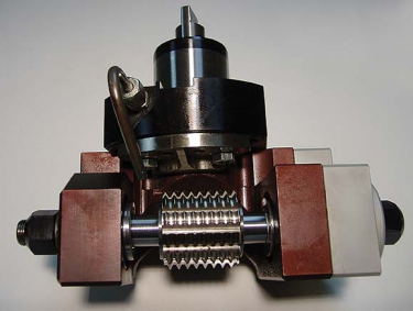
MD Tooling's gear hobbing tool allows a job that used to be moved to a customer's mill to be kept on a lathe. Image courtesy of MD Tooling.
“The capabilities of live tools are much greater now because of improvements in bearing technology,” he affirmed. “Our tools have taper roller bearings. With taper roller bearings, customers can push things harder.”
The bearings have tapered inner- and outer-ring raceways and tapered rollers. Their conical design makes the motion of the bearings remain coaxial, with no sliding motion between the raceways and the OD of the rollers. The conical geometry creates a linear contact area—rather than the single-point contact of spherical bearings—allowing greater loads to be carried.
“We’ve been slowly segueing into the taper roller bearings on 6,000-rpm and under [tools] for the last 5, 6 years,” Hansen said.
Bickham of ITI Tooling said the newest trend in live tooling is higher speeds. Beyond gear and bearing technology, another enabler of speed has been repositioning the turret motor to allow direct-drive powering of the tool, he said. In the early 1990s, tool-turret and live-tool maker Sauter, which ITI distributes, developed a motor and transmission system to replace what had been a two-motor live-tooling system—one for indexing the tool turret and another to drive the live tools.

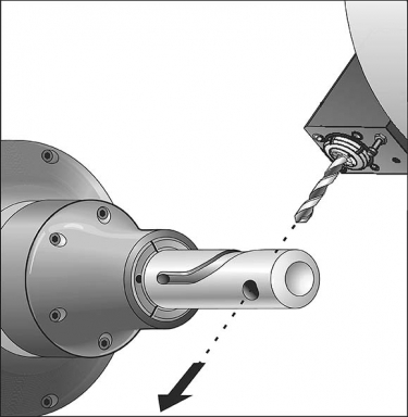
Live tools can be used for axial (above) and radial (below) cutting. Image courtesy of Haas Automation.
“Sauter developed a single- motor live-tool turret, where the transmission took place within the gear box of the turret, to change over from indexing from a station-to-station mode to the driving of the tool,” Bickham said. “And that eliminated the need for a second motor and a second drive.”
That was a great innovation at the time, he noted, but it limited the power of the tooling. “If the motor is at the end of a drivetrain and you have a shaft and now a bevel gear and another connection, you’re losing speed and torque and efficiency.”
Sauter’s newest designs address this problem by changing the location of the motor, Bickham explained. “Now they’ve moved the motor from the rear of the turret,” where it had to run through a transmission, “and moved it to the front of the turret, inside the tool disc, so there’s transmission from the arbor of the motor directly to the tool. Traditional lathes with live tooling could run at maybe 6,000 rpm. We can now run at 12,000 rpm.”
Gear-ratio toolholders can increase speeds even further, he noted. With these, “you can input 6,000 rpm and get 12,000 out—or 18,000 or 24,000, depending on the machine. We also work with tapping-head maker Tapmatic and with electro-spindle companies. Now a live tool can be mounted into a turret and be run up to 60,000 rpm. Speed is the thing.”
Contact Details
Contact Details

Contact Details
Contact Details
Related Glossary Terms
- arbor
arbor
Shaft used for rotary support in machining applications. In grinding, the spindle for mounting the wheel; in milling and other cutting operations, the shaft for mounting the cutter.
- centers
centers
Cone-shaped pins that support a workpiece by one or two ends during machining. The centers fit into holes drilled in the workpiece ends. Centers that turn with the workpiece are called “live” centers; those that do not are called “dead” centers.
- computer numerical control ( CNC)
computer numerical control ( CNC)
Microprocessor-based controller dedicated to a machine tool that permits the creation or modification of parts. Programmed numerical control activates the machine’s servos and spindle drives and controls the various machining operations. See DNC, direct numerical control; NC, numerical control.
- feed
feed
Rate of change of position of the tool as a whole, relative to the workpiece while cutting.
- flat ( screw flat)
flat ( screw flat)
Flat surface machined into the shank of a cutting tool for enhanced holding of the tool.
- gang cutting ( milling)
gang cutting ( milling)
Machining with several cutters mounted on a single arbor, generally for simultaneous cutting.
- lathe
lathe
Turning machine capable of sawing, milling, grinding, gear-cutting, drilling, reaming, boring, threading, facing, chamfering, grooving, knurling, spinning, parting, necking, taper-cutting, and cam- and eccentric-cutting, as well as step- and straight-turning. Comes in a variety of forms, ranging from manual to semiautomatic to fully automatic, with major types being engine lathes, turning and contouring lathes, turret lathes and numerical-control lathes. The engine lathe consists of a headstock and spindle, tailstock, bed, carriage (complete with apron) and cross slides. Features include gear- (speed) and feed-selector levers, toolpost, compound rest, lead screw and reversing lead screw, threading dial and rapid-traverse lever. Special lathe types include through-the-spindle, camshaft and crankshaft, brake drum and rotor, spinning and gun-barrel machines. Toolroom and bench lathes are used for precision work; the former for tool-and-die work and similar tasks, the latter for small workpieces (instruments, watches), normally without a power feed. Models are typically designated according to their “swing,” or the largest-diameter workpiece that can be rotated; bed length, or the distance between centers; and horsepower generated. See turning machine.
- milling
milling
Machining operation in which metal or other material is removed by applying power to a rotating cutter. In vertical milling, the cutting tool is mounted vertically on the spindle. In horizontal milling, the cutting tool is mounted horizontally, either directly on the spindle or on an arbor. Horizontal milling is further broken down into conventional milling, where the cutter rotates opposite the direction of feed, or “up” into the workpiece; and climb milling, where the cutter rotates in the direction of feed, or “down” into the workpiece. Milling operations include plane or surface milling, endmilling, facemilling, angle milling, form milling and profiling.
- milling machine ( mill)
milling machine ( mill)
Runs endmills and arbor-mounted milling cutters. Features include a head with a spindle that drives the cutters; a column, knee and table that provide motion in the three Cartesian axes; and a base that supports the components and houses the cutting-fluid pump and reservoir. The work is mounted on the table and fed into the rotating cutter or endmill to accomplish the milling steps; vertical milling machines also feed endmills into the work by means of a spindle-mounted quill. Models range from small manual machines to big bed-type and duplex mills. All take one of three basic forms: vertical, horizontal or convertible horizontal/vertical. Vertical machines may be knee-type (the table is mounted on a knee that can be elevated) or bed-type (the table is securely supported and only moves horizontally). In general, horizontal machines are bigger and more powerful, while vertical machines are lighter but more versatile and easier to set up and operate.
- outer diameter ( OD)
outer diameter ( OD)
Dimension that defines the exterior diameter of a cylindrical or round part. See ID, inner diameter.
- tap
tap
Cylindrical tool that cuts internal threads and has flutes to remove chips and carry tapping fluid to the point of cut. Normally used on a drill press or tapping machine but also may be operated manually. See tapping.
- tapping
tapping
Machining operation in which a tap, with teeth on its periphery, cuts internal threads in a predrilled hole having a smaller diameter than the tap diameter. Threads are formed by a combined rotary and axial-relative motion between tap and workpiece. See tap.
- turning
turning
Workpiece is held in a chuck, mounted on a face plate or secured between centers and rotated while a cutting tool, normally a single-point tool, is fed into it along its periphery or across its end or face. Takes the form of straight turning (cutting along the periphery of the workpiece); taper turning (creating a taper); step turning (turning different-size diameters on the same work); chamfering (beveling an edge or shoulder); facing (cutting on an end); turning threads (usually external but can be internal); roughing (high-volume metal removal); and finishing (final light cuts). Performed on lathes, turning centers, chucking machines, automatic screw machines and similar machines.
Author

Michael Anderson, former senior editor at Cutting Tool Engineering magazine, holds a master's degree in written communication from Eastern Michigan University. He has been professionally writing about manufacturing technology since 1998, including more than 10 years at the Society of Manufacturing Engineers.
Contributors
Heimatec Inc.
(847) 749-0633
www.heimatecinc.com
ITI Tooling Co. Inc.
(888) 88-ROTATE
www.ititooling.com
Koma Precision Inc.
(800) 249-5662
www.komaprecision.com
MD Tooling LLC
(877) 918-6657
www.mdtooling.com