Few 5-axis machine users ever cut an impeller. Yet impellers are repeatedly used as examples by CAD/CAM software vendors and machine tool builders. There is a practical reason for this. Impellers have challenging shapes that ably demonstrate 5-axis capabilities.
Because the impeller offers so many 5-axis challenges, I will use one as an example to explain common 5-axis machining issues. Even if you don’t cut impellers, this information likely applies to some aspects of your multiaxis machining.
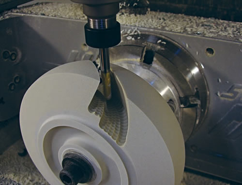
Courtesy of CNC Software
When 5-axis plunge roughing, tool deflection is minimal because cutting forces are aligned with the cutter’s center axis, dramatically extending tool life.
In the early ’70s before CAD/CAM systems, the design of an impeller’s individual blades, or vanes, was based on projected, synchronized and smooth machine motions. Those pure designs where perfectly suited for swarf 5-axis tool motions, where it was possible to cut the blades with the side of a tool, usually a straight or bull nose corner-radius cutter. (Swarf refers to the tilted or twisted blade wall surfaces that are cut with the side of a tool.)
The design of modern impeller blades is not as pure. They are often designed with solid-modeling CAD packages, allowing the user to create shapes that are highly complex but may have a total disregard for manufacturing efficiency.
Most of the blades are tall on one end, usually near an impeller’s center, and short on the other. Modern blades are often “warped,” making swarf cutting impossible because they have to be cut in multiple steps with the nose of a tapered ballnose cutter, as the tool axis is manipulated to avoid collisions.
Machining impellers from a blank involves turning, roughing the excess material from between the blades, semifinishing the floor and the blades and then finishing the floor and the blades. If a multitasking machine is available, these operations can be done in one or, possibly, two setups.
It is common practice to rough the excess material from between the blades using 3+2 machining techniques. This is done by indexing the rotary axes, locking them in place to keep the 5-axis machine in its most rigid state and then attacking the exposed excess material using simple 3-axis toolpaths. The drawback of this approach is that it is not always possible to remove all the excess material. It is hard to keep track of in-process material and it is necessary to overlap between cuts—causing too many “air” cuts. Furthermore, the area between the blades is often deep and narrow—a bad combination because it requires long, skinny tools. These tools don’t do well side-cutting, especially when the cutting pressures constantly change, causing variable amounts of deflection. This in turn causes vibration, shortens tool life and imparts a poor finish.
Modern CAM systems offer an effective solution—5-axis plunge roughing. The excess material is picked away by limiting the plunge depth and step-over in an onion skin-type manner. All the motions are still executed in the machine’s rigid 3+2 state. Tool deflection is minimal because cutting forces are aligned with the cutter’s center axis, dramatically extending tool life. These toolpaths not only keep track of the in-process material at every step, they also trim the toolpath to the initial stock model using “stock recognition” so wasteful air cuts are not generated. Case studies have shown that roughing cycle times can be reduced by more than 60 percent compared to traditional roughing techniques.
Finishing the floor between the blades is fairly simple when employing a zig-zag cut pattern that starts from the center and extends towards the outside perimeter. This motion maintains a constant climb-cut. Extending the entry and exit motions imparts a smooth, uniform finish. Tool axis can be controlled by forcing the center of the tool axis along a chain placed in the middle of the gap between the blades.
Finishing impeller blades is the biggest challenge. The individual blades of an impeller are often thin, warped, short on one end, tall on the other and close together. It is desirable to keep the cut pattern parallel to the hub surface. It is also preferable to cut the whole blade in one continuous motion to avoid leaving undesired tool marks on the workpiece.
Semifinishing and finishing toolpaths are basically the same, except for the amount of material left and the step-over value. Care must be taken to leave plenty of material for finishing. If done properly, the finish cut will “free” the blade gradually, avoiding any vibration, even on very thin blades. Tapered-end ballnose cutters are preferred for maximum rigidity.
The challenging part of this operation is dynamically controlling the tool axis, as the tool gradually spirals down the blade. Your CAM system must be capable of continuously monitoring the tool tip, flute, arbor and toolholder. The CAM system must not only monitor, but also take action if a user predefined near-miss is imminent. For example, tilt the tool in the side tilt direction if it comes too close to the next blade, or retract the tool along a tool axis if it comes too close to the floor surface and link these motions in a smooth synchronized motion by considering the available machine tool capabilities.
Modern CAD/CAM systems allow you to control all aspects of 5-axis machining: the cut pattern, the tool axis direction as the tool is following that cut pattern and the exact contact point of the tool tip as it touches the drive surfaces. A complete package also allows you to watch a virtual machine simulate the entire cutting process while developing it, rather than using an expensive 5-axis machine as a verification tool.
Five-axis machining is a growing, challenging and exciting field. Some think it is hard to do, but “hard to do” always comes down to training. Didn’t you initially find it hard to ride a bicycle? CTE
About the Author: Karlo Apro is senior applications engineer for CNC Software Inc., Tolland, Conn., and author of the book “Secrets of 5-Axis Machining,” published by Industrial Press Inc., New York. For more information about the company’s Mastercam CAD/CAM software, visit www.mastercam.com, call (800) 228-2877 or enter #360 on the Information Services Card.
Related Glossary Terms
- arbor
arbor
Shaft used for rotary support in machining applications. In grinding, the spindle for mounting the wheel; in milling and other cutting operations, the shaft for mounting the cutter.
- computer numerical control ( CNC)
computer numerical control ( CNC)
Microprocessor-based controller dedicated to a machine tool that permits the creation or modification of parts. Programmed numerical control activates the machine’s servos and spindle drives and controls the various machining operations. See DNC, direct numerical control; NC, numerical control.
- computer-aided design ( CAD)
computer-aided design ( CAD)
Product-design functions performed with the help of computers and special software.
- computer-aided manufacturing ( CAM)
computer-aided manufacturing ( CAM)
Use of computers to control machining and manufacturing processes.
- finish cut
finish cut
Final cut made on a workpiece to generate final dimensions or specified finish. Often made using reduced feeds and higher speeds. Generally, the better the surface finish required, the longer the finish cut takes. Also, the final cut taken on an electrical-discharge-machined part.
- parallel
parallel
Strip or block of precision-ground stock used to elevate a workpiece, while keeping it parallel to the worktable, to prevent cutter/table contact.
- step-over
step-over
Distance between the passes of the toolpath; the path spacing. The distance the tool will move horizontally when making the next pass. Too great of a step-over will cause difficulty machining because there will be too much pressure on the tool as it is trying to cut with too much of its surface area.
- swarf
swarf
Metal fines and grinding wheel particles generated during grinding.
- toolholder
toolholder
Secures a cutting tool during a machining operation. Basic types include block, cartridge, chuck, collet, fixed, modular, quick-change and rotating.
- toolpath( cutter path)
toolpath( cutter path)
2-D or 3-D path generated by program code or a CAM system and followed by tool when machining a part.
- turning
turning
Workpiece is held in a chuck, mounted on a face plate or secured between centers and rotated while a cutting tool, normally a single-point tool, is fed into it along its periphery or across its end or face. Takes the form of straight turning (cutting along the periphery of the workpiece); taper turning (creating a taper); step turning (turning different-size diameters on the same work); chamfering (beveling an edge or shoulder); facing (cutting on an end); turning threads (usually external but can be internal); roughing (high-volume metal removal); and finishing (final light cuts). Performed on lathes, turning centers, chucking machines, automatic screw machines and similar machines.