Some workpieces, like those that are oddly shaped, large or delicate, can be a real pain in the neck. Delicate geometries, thin walls and shapes more flexible than a ballerina—what’s the best way to securely grab hold of them? Gerard Vacio, workholding systems specialist at BIG Kaiser Precision Tooling Inc., Hoffman Estates, Ill., said the economics of machining these parts means spending more time and money up front to figure out the best way to fixture them.
“Nobody wants to do that,” he said. “Designing and building the fixture often ends up eating all the profits from the job. That’s why a lot of shops turn down this kind of work. Unless you have some influence over part design, where you can add features or tweak geometry to make a part easier to hold, it’s often a losing proposition. Even companies that build their own products don’t always realize the possibilities of lobbying the engineering department to make parts more manufacturable.”
Design for manufacturability aside, some companies thrive on making complex parts. Vacio said these shops use their creativity and engineering brilliance to find the most economical solution. “No one has yet invented a tractor beam that 's going to solve workholding problems. The result is that people end up tackling each element of a difficult workpiece individually.”
Examples include sandbags placed on the part to reduce vibration, or the use of specialty glue or low-melt potting compound to support delicate areas during machining. Often, you can use part features, such as a threaded boss or dowel pin holes, to locate and clamp a part. “There’s no one solution. It’s a matter of utilizing whatever’s available,” Vacio said.
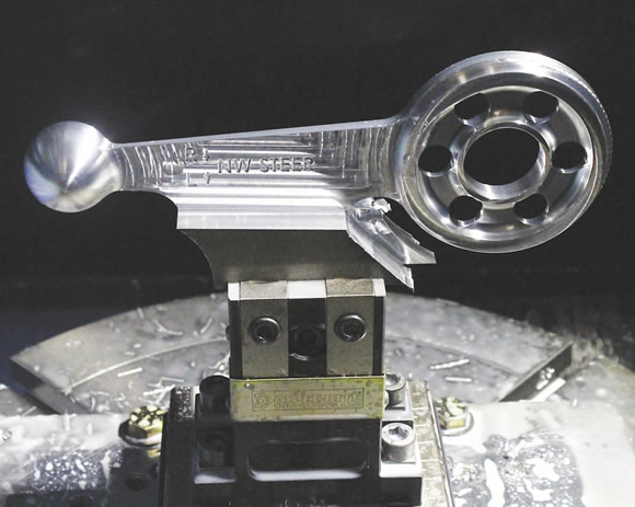
A landing gear steering lever for the Viking Twin Otter aircraft begins as a 10 "×4 "×1.5 " block of 7075 aluminum and is mostly completed in one operation. Image courtesy Mitee-Bite Products.
He recommends careful planning, because the first operation can make or break the ability to grip difficult-to-hold parts later on. This is one job 5-axis machining centers excel at, he explained. A part can be gripped once, when it has the most material available, then tipped and rotated until the machining is nearly completed. With the right strategy and a little luck, all that remains is refixturing the part and a quick saw cut or a slice with a wire EDM and the part drops off complete.
Even without a 5-axis machine, this use of sacrificial material is a common practice with oddly shaped workpieces. David Bishop, general manager of workholding manufacturer Mitee-Bite Products LLC, Center Ossipee, N.H., said the carrier method is an easy solution for oddballs. “It’s a fun challenge to place as many parts as possible in the machining envelope and complete the part in two operations or less. Even an extra 1/16 " of material on the bottom of the workpiece is often enough to hang on to. By gripping low, you can machine the top and sides, then nest the part in machinable jaws or a quick-change fixture of some kind to mill away the gripping surface and at the same time finish the workpiece.”
One excellent example of this is an aluminum landing gear component made by one of Mitee-Bite’s customers, Straightline Precision Industries Inc., Sidney, B.C. (see photo above). Here, the part was machined nearly complete on a tilt-rotary table—all that remains is to grip the center section and remove the carrier. Another approach is locating on internal part features. A pair of adjacent holes makes a nifty place to grab a part, which is why Mitee-Bite and other workholding providers carry a range of expansion clamps and internal collets to grip a 3/16 " diameter or smaller. Bishop pointed out a recent example of this with Haas Automation, where a rotary table was used to machine the part in several operations, the final one locating off a pair of 1.375 "-dia. bores (see photo below).
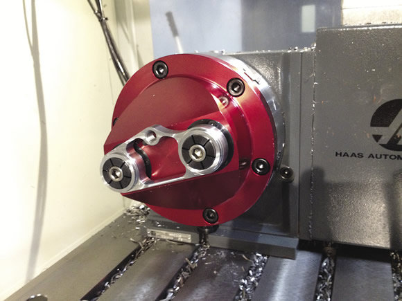
The final operation on this part uses a Haas HRC210 rotary table and locates two 13/8 " diameter bores to hold the part while several holes and slots are machined on the profile. Image courtesy Mitee-Bite Products.
Lastly, Bishop said don’t forget about air power. Vacuum chucks are a great way to secure large, flat workpieces. As proof, Mitee-Bite customer Fore Machine Co., Fort Worth, Texas, used six interconnected vacuum chucks together with an aluminum top plate to grip a pair of Ti6Al4V titanium deck plates used on Bell UH-1 Iroquois helicopters (the Huey), allowing it to machine the entire top surface in a single operation, without the need for toe clamps or clamping screws.
If you have a difficult part and need help, don’t be afraid to ask. Many workholding providers offer consulting services, from free ideas and advice to complete turnkey solutions. One is Stace-Allen Chucks Inc., Indianapolis. “Good fixture and workholder design often comes down to experience, " said Mechanical Engineer Adam Homan. "We get requests from manufacturing engineers that may launch a new part every couple years. We’re launching new parts monthly.”
It’s important to start from the ground up and consider workpiece quantity, the machine tool being used, raw material and cutting forces. “We start by looking at the part geometry and the GD&T (geometric dimensioning and tolerancing) associated with it, " Homan said. "That tells us where we have to grip and locate, and whether we can use a chuck, a collet or some other kind of fixture. Then we look at machining parameters. For example, the highest spindle speed dictates the type of workholding we can use. Part geometry is a factor too, because sometimes it looks like a chuck will work, but because of the GD&T, the jaws may get too long and centrifugal force will pull them open. It’s a balancing act.”
One of Homan’s balancing acts was a high-volume automotive part, turned on a Wasino gang-style CNC lathe (see photo on below). A 5-jaw collet chuck gripped the inner hub on the P/M part, while a matching set of locating surfaces supported its outer ears. Because automation was used, part locating confirmation was done via an inline air sensor. Homan also equipped the chuck with through-spindle coolant.
Another notable application was a cast iron forklift component, machined on a Mazak Quick-Turn lathe. “Swing clamps were really the only way to hold that part in place,” Homan said. “The clamps are commercially available and provide up to 1,250 lbs. of clamping force each. The part locates off a set of round and diamond pins and maintains consistent centerline within 0.0005 " of that face.”
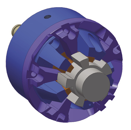
A 5-jaw collet chuck, equipped with air seat confirmation and through-the-spindle coolant, grips an automotive part. Image courtesy Stace-Allen Chucks.
Homan said these were unique examples of what’s possible. “Neither of these have incredibly tight tolerances—they just had weird geometries and orientation strategies. Both were complete one-offs. Whenever possible, we like to use one of our standard chucks rather than a custom, as there are fewer unknowns. But with weird parts like this, it often needs to be designed from the ground up.”
Workholding for challenging parts isn’t a science. Imagination, experience and a handle on what’s available from suppliers like these are just as important as engineering and design skills. But there’s plenty of help available the next time an oddly shaped part crosses your desk. Maybe now you won’t be so quick to no-quote it. CTE
About the Author: Kip Hanson is contributing editor for CTE. Contact him at (520) 548-7328 or [email protected].
Related Glossary Terms
- centers
centers
Cone-shaped pins that support a workpiece by one or two ends during machining. The centers fit into holes drilled in the workpiece ends. Centers that turn with the workpiece are called “live” centers; those that do not are called “dead” centers.
- chuck
chuck
Workholding device that affixes to a mill, lathe or drill-press spindle. It holds a tool or workpiece by one end, allowing it to be rotated. May also be fitted to the machine table to hold a workpiece. Two or more adjustable jaws actually hold the tool or part. May be actuated manually, pneumatically, hydraulically or electrically. See collet.
- collet
collet
Flexible-sided device that secures a tool or workpiece. Similar in function to a chuck, but can accommodate only a narrow size range. Typically provides greater gripping force and precision than a chuck. See chuck.
- computer numerical control ( CNC)
computer numerical control ( CNC)
Microprocessor-based controller dedicated to a machine tool that permits the creation or modification of parts. Programmed numerical control activates the machine’s servos and spindle drives and controls the various machining operations. See DNC, direct numerical control; NC, numerical control.
- coolant
coolant
Fluid that reduces temperature buildup at the tool/workpiece interface during machining. Normally takes the form of a liquid such as soluble or chemical mixtures (semisynthetic, synthetic) but can be pressurized air or other gas. Because of water’s ability to absorb great quantities of heat, it is widely used as a coolant and vehicle for various cutting compounds, with the water-to-compound ratio varying with the machining task. See cutting fluid; semisynthetic cutting fluid; soluble-oil cutting fluid; synthetic cutting fluid.
- electrical-discharge machining ( EDM)
electrical-discharge machining ( EDM)
Process that vaporizes conductive materials by controlled application of pulsed electrical current that flows between a workpiece and electrode (tool) in a dielectric fluid. Permits machining shapes to tight accuracies without the internal stresses conventional machining often generates. Useful in diemaking.
- fixture
fixture
Device, often made in-house, that holds a specific workpiece. See jig; modular fixturing.
- flat ( screw flat)
flat ( screw flat)
Flat surface machined into the shank of a cutting tool for enhanced holding of the tool.
- lathe
lathe
Turning machine capable of sawing, milling, grinding, gear-cutting, drilling, reaming, boring, threading, facing, chamfering, grooving, knurling, spinning, parting, necking, taper-cutting, and cam- and eccentric-cutting, as well as step- and straight-turning. Comes in a variety of forms, ranging from manual to semiautomatic to fully automatic, with major types being engine lathes, turning and contouring lathes, turret lathes and numerical-control lathes. The engine lathe consists of a headstock and spindle, tailstock, bed, carriage (complete with apron) and cross slides. Features include gear- (speed) and feed-selector levers, toolpost, compound rest, lead screw and reversing lead screw, threading dial and rapid-traverse lever. Special lathe types include through-the-spindle, camshaft and crankshaft, brake drum and rotor, spinning and gun-barrel machines. Toolroom and bench lathes are used for precision work; the former for tool-and-die work and similar tasks, the latter for small workpieces (instruments, watches), normally without a power feed. Models are typically designated according to their “swing,” or the largest-diameter workpiece that can be rotated; bed length, or the distance between centers; and horsepower generated. See turning machine.
- milling machine ( mill)
milling machine ( mill)
Runs endmills and arbor-mounted milling cutters. Features include a head with a spindle that drives the cutters; a column, knee and table that provide motion in the three Cartesian axes; and a base that supports the components and houses the cutting-fluid pump and reservoir. The work is mounted on the table and fed into the rotating cutter or endmill to accomplish the milling steps; vertical milling machines also feed endmills into the work by means of a spindle-mounted quill. Models range from small manual machines to big bed-type and duplex mills. All take one of three basic forms: vertical, horizontal or convertible horizontal/vertical. Vertical machines may be knee-type (the table is mounted on a knee that can be elevated) or bed-type (the table is securely supported and only moves horizontally). In general, horizontal machines are bigger and more powerful, while vertical machines are lighter but more versatile and easier to set up and operate.
- sawing machine ( saw)
sawing machine ( saw)
Machine designed to use a serrated-tooth blade to cut metal or other material. Comes in a wide variety of styles but takes one of four basic forms: hacksaw (a simple, rugged machine that uses a reciprocating motion to part metal or other material); cold or circular saw (powers a circular blade that cuts structural materials); bandsaw (runs an endless band; the two basic types are cutoff and contour band machines, which cut intricate contours and shapes); and abrasive cutoff saw (similar in appearance to the cold saw, but uses an abrasive disc that rotates at high speeds rather than a blade with serrated teeth).
- wire EDM
wire EDM
Process similar to ram electrical-discharge machining except a small-diameter copper or brass wire is used as a traveling electrode. Usually used in conjunction with a CNC and only works when a part is to be cut completely through. A common analogy is wire electrical-discharge machining is like an ultraprecise, electrical, contour-sawing operation.
Author

Kip Hanson is a contributing editor for Cutting Tool Engineering magazine. Contact him by phone at (520) 548-7328 or via e-mail at [email protected].