It’s ironic. Tell a shop owner or production engineer to mount a mechanical 3-jaw chuck on a CNC lathe and they’ll look at you as though you’re wearing a duck on your head. Why do they then turn around and put old-fashioned, hand-cranked vises on vertical machining centers? A basic hydraulic vise setup for a VMC can cost between $1,700 and $4,000—roughly the same price as a hydraulic workholder on a lathe—and provide far more reliable and consistent clamping than mechanical units. So what gives?
Getting Comfortable
According to Mike Antos, application engineer at Cleveland-based workholding and lifting products manufacturer Jergens Inc., fewer than 10 percent of shops use hydraulic vises on their machining centers. This lack of acceptance is due largely to shops going with what they know. “Most machine shops have always used mechanical vises,” he said. “There’s a comfort factor there. Then along comes the vise salesman and the word ‘hydraulics’ comes up. That can be somewhat intimidating.”
There’s nothing to be scared of. Hydraulic systems make your car stop at red lights. They compact the trash you put on the curb and raise the seat when you’re getting a haircut. Installing a hydraulic pump and plumbing a few lines is no more complicated than fixing a leaky toilet seal.
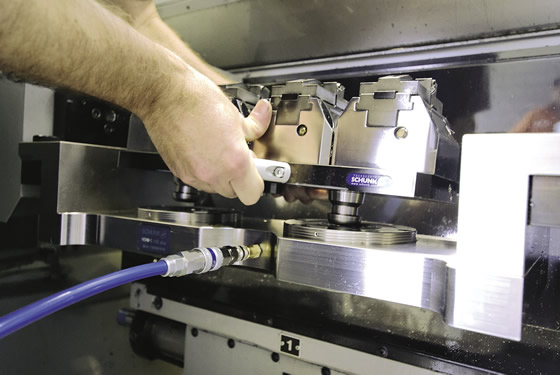
Courtesy of Schunk
Four Schunk KSH 4" hydraulic vises are changed out using a Vero-S quick change-pallet system with integrated hydraulic lines. This type of setup avoids exposing hydraulic lines to chips and cutting fluid during machining.
Machine tool builders are partially to blame for the lack of acceptance of hydraulic vises. The cost of a chuck and the hydraulic system to power it are already rolled into the price of most CNC lathes—if they weren’t, shop owners might be inclined to pull out their red Sharpie and strike them off the purchase order. But if builders were to equip that shiny new machining center with a hydraulic vise, you can bet a Ben Franklin that machinists would use it.
Money is a big consideration. A fully plumbed trio of hydraulic vises equipped with automatic clamping can set you back $40,000 or more. If your needs are more modest, a basic hydraulic starter kit and 6" vise sells for significantly less. Either way, it’s a lot of money, considering you can buy 20 commodity mechanical vises for the price of a starter package.
Consider the Benefits
“It’s our job to get shops to recognize the benefits of hydraulic workholding—reduced setup time, clamping consistency and improved part quality,” Antos said, noting Jergens covers it every day with customers.
How does a hydraulic vise make better parts? Antos explained that predictable clamping forces are a key determinant of part quality. Savvy shops have long equipped their machinists with torque wrenches to tighten mechanical vises, especially when machining delicate or thin-walled parts. Hydraulics eliminate this need. Dial in the desired pressure from 10 to 10,000 lbs. and hydraulics deliver exactly that clamping force, day in and day out, and do so with minimal maintenance.
“Considering the shortage of skilled operators, hydraulic vises simplify machine operation while providing predictable part positioning,” Antos said. But perhaps the biggest benefit is improved productivity. Pushing a button to clamp four vises at once beats reaching for the wrench and cranking it for each vise—the former takes less than a second, the latter 30 seconds or more. These small gains add up. “If you can save 2 hours a day, you’ve gained 500 hours of extra machining time a year,” he added.
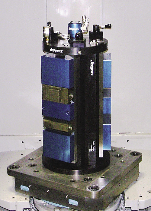
Courtesy of Jergens
A Jergens three-sided tooling column, equipped with hydraulic twin vises, is mounted on a Ball Lock pallet.
Antos explained that vises can be plumbed to clamp and unclamp individually or all at once, depending on how the valves are installed. Better yet, even the simple act of pushing a button can be avoided with a little electrical work and the right plumbing—wiring hydraulic valves into a CNC is a straightforward exercise, one that enables automated clamping and robotic part handling.
There are several considerations when purchasing hydraulic vises. The first is the type of vise and its stroke length. Garth Dexter, general manager of Planet Products Corp., a Cincinnati-based contract manufacturer and machine tool accessory supplier, explained that there are two types of hydraulic vises: single-acting, which uses spring pressure to open the vise, and double-acting, which uses hydraulic power to clamp and unclamp the vise. All Planet vises are double-acting.
Dexter said double-acting vises are beneficial for robotic applications, because the vises will definitely be open when a gripper arm grabs an otherwise immovable workpiece. Purveyors of single-acting vises might argue theirs will be open as well, but none would disagree that pump selection is dependent on vise quantity, size and type.
Planet’s standard vises have 2½" of stroke travel, and its self-centering model has 4". Competitive hydraulic vises typically offer ⅜" or less, Dexter claimed. Still, that’s plenty of travel for machining all but the most randomly shaped castings or when clamping on a deep undercut. The biggest advantage to more travel, he said, is flexibility. “In a job shop, for example, where you have great variation in part size, or families of parts, you can clamp multiple sizes in the same setup.”
All Pumped Up
Long stroke or short, most hydraulic vises allow the movable jaw to slide close to the workpiece and lock into place. This minimizes jaw travel and cuts the load or unload time to less than 1 second. The primary consideration in vise selection, however, isn’t stroke length, but pump type, because vises require sufficient oil and pressure to do their job. As pressure and/or volume needs increase, a commensurately stronger pump is called for. Pump selection, however, should come after the workholding and plumbing have been designed; otherwise, there may not be enough “oomph” to push the necessary amount of oil through the system.
Pumps come in two basic styles: air-over-hydraulic and electric. Air-driven pumps work by “boosting” compressed air at ratios from 20:1 to 70:1 or more. This makes them slightly less capable than electric pumps in terms of clamping pressure. At 100 psi, for example, a typical air pump might output 5,000 lbs. of clamping pressure. This is still plenty of force for most applications, but much less than the 7,500 lbs. to 10,000 lbs. available from many comparably sized electric pumps.
Boosters are the “little engines that could” of the air-driven pump family. They displace a fixed amount of oil and can only be used with single-acting vises, but considering their low price tag—about $500 each—they’re an option for shops not willing to commit $2,000 and up for a more capable air or electric pump. Air and electric pumps have oil reservoirs best measured in gallons and pressures far greater than is possible with a booster pump, and are clearly the way to go for most job shops.
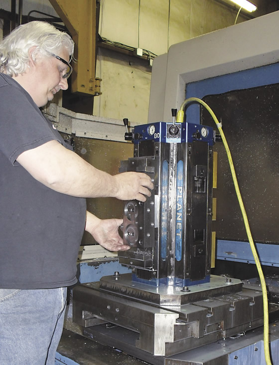
Courtesy of Planet Products
An operator loads workpieces on Planet Products’ production floor. The yellow cord is a removable 25v DC power supply for the integral pump unit. Hydraulic pressure is maintained via an internal accumulator.
In the electric vs. air debate, Dexter said: “Air-driven pumps are easier to install. You don’t need electrical power. They also self-limit—they go up to a certain pressure and stop, whereas electric pumps need a pressure switch to tell them when to stop pumping. But, for some applications, we’ll utilize an electric pump with a high-rpm motor and very fine pump adjustment. This gives high pressure without the risk of slamming the vise shut.”
Pump size and type ultimately come down to the pressure and volume required for an application. Yet David Vilcek, engineering project manager for Carr Lane Roemheld Manufacturing Co., Fenton, Mo., might tell you to ditch all those pumps and lines and select its hydra-mechanical vises, which offer the benefits of hydraulic workholding without the plumbing.
“Hydra-mechanical vises utilize a self-contained hydraulic system,” Vilcek said. “Like a mechanical vise, you turn a crank until the movable jaw touches the part.” Once it touches the part, however, the similarities change—hydra-mechanical vises have a small detent on the side of the vise. “It just takes a little pop with your hand to engage. When you turn the crank, it advances an internal piston that builds hydraulic pressure, resulting in a very high clamping force of up to 12,000 lbs. on our 160mm vise.”
This isn’t a one-trick pony for the company. Like its competitors, Carr Lane Roemheld also offers externally powered hydraulic vises. Regardless of the brand, it’s important to select the same qualities in a hydraulic vise as a mechanical one. “One key feature is the vise base itself,” Vilcek said. “Those machined out of steel rather than cast iron are more robust. Look for precision-ground guide ways and locating surfaces, casehardened to several millimeters deep.”
Vilcek considers hydraulic workholding a flexible tool for fixturing—not just some “plain old vise”—and a good intermediate step between pure mechanical systems and dedicated fixtures. Hydraulic workholders quickly adjust to part sizes from ½" (12.7mm) or smaller to 10" (254mm) or more across, he added. “With delicate parts, you can dial the pressure down for a gentle touch. When you need to rip, crank it up. Either way, you’re sure to get the same clamping force every time.”
Going Dense
Suppose your best electronics customer orders 1,000 2"-wide, thin-wall aluminum housings per month. Sold on the value of hydraulic workholders, you use high-quality, 4 " (101.6mm) hydraulic vises to set up the tombstones on a horizontal machining center, but immediately hit a snag: Because the vises are nearly as tall as the tombstone itself, you can only fit one vise per face. Even with a two-sided production vise, that’s only eight parts per cycle—so much for going lights-out.
The good news is several hydraulic vise manufacturers offer compact versions. One is the KSH series hydraulic clamping block from Schunk Inc., Morrisville, N.C. With vise bodies as small as 2½" (64mm) square, you could easily quadruple the number of clamping stations in the scenario just described. Workholding Product Manager Brad Evans said high part density and rapid changeover are productivity enhancers, and both are supported by hydraulic workholding.
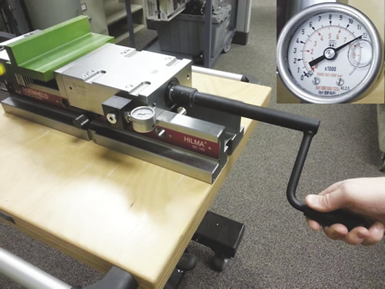
Courtesy of Carr Lane Roemheld Manufacturing
Hydra-mechanical vises from Carr Lane Roemheld offer the hydraulic advantages of precision and high clamping force but with no pumps or retrofitting, according to the company. This NC device can be operated with one hand, with internal hydraulics generating 12,000 lbs. of clamping force on the 160mm model.
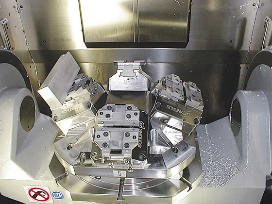
Courtesy of Schunk
Four Schunk KSH 6" hydraulic vises on a pyramidal fixture base, mounted on a 5-axis mill, permits machining four parts in one setup.
“Shops aiming at maximum productivity will order their vises with quick-change jaws,” Evans said. “They can then mount a number of vises on a zero-point or other quick-change pallet system and plumb the whole thing with hydraulics. Now, when a new job comes along, they can machine the jaws offline, load the pallet into the CNC machine and go. There’s no time lost dialing in the vise or finding the zero point.”
Prepare yourself for some sticker shock, though: As mentioned previously, a hydraulic system such as this might mean investing 20 percent or more of the machine’s purchase price in workholding. Over the long-term, however, that’s a small price to pay for the flexibility, accuracy and productivity gained with hydraulics. If you’re not quite ready to bite the bullet on a high-density or multivise system, go with a starter kit and a booster pump. It’s all about keeping the spindle running and the machine doors closed.
“You can’t have a guy standing in front of a single machine anymore,” Evans said. “Today’s machinists need to run three or four machines, and one of the best ways to do that is with hydraulic workholding.” CTE
Courtesy of Dapra
Dapra’s HydraVise offers 18,000 lbs. of clamping force with 100-psi shop air.
Big and strong vises
Matt Milhomens, inside technical sales rep for Dapra Corp., Bloomfield, Conn., is the guy to call if you need a vise with a high clamping force. His company’s 8 " HydraVise has enough to restrain an elephant—100 psi of shop air generates 18,000 lbs. of clamping force.
It works by rotating a spindle on the end of the vise’s movable jaw until it makes contact with the workpiece, then backing the spindle off three clicks counterclockwise, Milhomens said. At that point, you can manually open and close the vise with a valve mounted on the vise or automatically through a solenoid connected to the CNC.
Aside from the benefit of high clamping force, Milhomens said there’s no need for a pump with the HydraVise. “Once clamped, the HydraVise stays closed, even if you lose air pressure.”
The HydraVise accepts workpieces up to 15 " across. For bigger parts, Milhomens suggests the 6 "-wide ProVise, which is similar to the HydraVise but without the hydraulic cylinder. The advantage to the ProVise is that it’s expandable and can accommodate workpieces 31 " across or larger. That’s because the body of the ProVise can be separated—sort of like sawing a 6 " commodity vise in two. Bolt the fixed jaw wherever it’s needed and the movable jaw directly opposite it, then set the workpiece between the two and start cranking.
“We show the ProVise on the same brochure as the HydraVise, but it’s not hydraulic,” Milhomens said. “The clamping pressure is generated by a system of rollers and wedges. It’s entirely mechanical.” The price depends on size and model, but a ballpark price is about $5,000.
—K. Hanson
When is a vise not a vise?
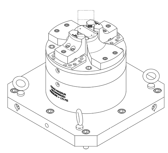
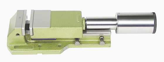
Courtesy of Stace Allen
Mounting a 2-jaw hydraulic chuck on a milling machine is a viable alternative to conventional vises and provides strong gripping force and pullback against a positive stop.
Stace-Allen Chucks Inc. doesn’t make vises. But the Indianapolis-based workholding manufacturer can help you with other types of workholding. Mechanical Engineer and man-of-many-hats Adam Homan said hydraulic 2- and 3-jaw chucks are often good alternatives to vises, given the right workpiece. “One of our customers mills a lot of square aluminum bar stock. We used a 2-jaw chuck with a built-in hydraulic cylinder to grip those parts.”
Because turning and milling departments typically don’t share tooling, rolling a hydraulic chuck from a CNC lathe into the milling department is sort of like inviting a Packers fan to a Bears game. Homan defends this unusual workholding method by pointing out one aspect of lathe chucks that every lathe operator learns early on: pullback.
“In this customer’s case, we wanted to pull the workpiece against a positive stop,” he said. “Hydraulic vises exert force across the sides of the workpiece, but they don’t pull it down and into the locating surface like chucks do. This provides a very secure and accurate grip.”
Homan said the use of hydraulic chucks are on the rise for certain milling applications. “Some of the new 5-axis machining centers have a hydraulic supply that comes up through the middle of the table. It’s very easy to integrate a hydraulic chuck in this case and avoids any exposed hoses.” And because many 5-axis parts are machined in a manner similar to one turned on a CNC lathe—one at a time—using a lathe chuck might make sense, especially when cutting round stock. “Setup is simple. You always know where the center of the part is with a chuck.”
Hydraulic chucks are accurate to a couple tenths, self-contained, consistent as gravity and cost roughly the same as their rectangular counterparts. Maybe it’s time to think outside the box.
—K. Hanson
Contributors
Carr Lane Roemheld Manufacturing Co.
(636) 386-8022
www.clrh.com
Dapra Corp.
(800) 243-3344
www.dapra.com
Jergens Inc.
(877) 426-2504
www.jergensinc.com
Planet Products Corp.
(513) 984-5544
www.planet-products.com
Schunk Inc.
(800) 772-4865
www.us.schunk.com
Stace-Allen Chucks Inc.
(317) 632-2401
www.stace-allen.com
Related Glossary Terms
- backing
backing
1. Flexible portion of a bandsaw blade. 2. Support material behind the cutting edge of a tool. 3. Base material for coated abrasives.
- centers
centers
Cone-shaped pins that support a workpiece by one or two ends during machining. The centers fit into holes drilled in the workpiece ends. Centers that turn with the workpiece are called “live” centers; those that do not are called “dead” centers.
- chuck
chuck
Workholding device that affixes to a mill, lathe or drill-press spindle. It holds a tool or workpiece by one end, allowing it to be rotated. May also be fitted to the machine table to hold a workpiece. Two or more adjustable jaws actually hold the tool or part. May be actuated manually, pneumatically, hydraulically or electrically. See collet.
- computer numerical control ( CNC)
computer numerical control ( CNC)
Microprocessor-based controller dedicated to a machine tool that permits the creation or modification of parts. Programmed numerical control activates the machine’s servos and spindle drives and controls the various machining operations. See DNC, direct numerical control; NC, numerical control.
- cutting fluid
cutting fluid
Liquid used to improve workpiece machinability, enhance tool life, flush out chips and machining debris, and cool the workpiece and tool. Three basic types are: straight oils; soluble oils, which emulsify in water; and synthetic fluids, which are water-based chemical solutions having no oil. See coolant; semisynthetic cutting fluid; soluble-oil cutting fluid; synthetic cutting fluid.
- fixture
fixture
Device, often made in-house, that holds a specific workpiece. See jig; modular fixturing.
- gang cutting ( milling)
gang cutting ( milling)
Machining with several cutters mounted on a single arbor, generally for simultaneous cutting.
- lathe
lathe
Turning machine capable of sawing, milling, grinding, gear-cutting, drilling, reaming, boring, threading, facing, chamfering, grooving, knurling, spinning, parting, necking, taper-cutting, and cam- and eccentric-cutting, as well as step- and straight-turning. Comes in a variety of forms, ranging from manual to semiautomatic to fully automatic, with major types being engine lathes, turning and contouring lathes, turret lathes and numerical-control lathes. The engine lathe consists of a headstock and spindle, tailstock, bed, carriage (complete with apron) and cross slides. Features include gear- (speed) and feed-selector levers, toolpost, compound rest, lead screw and reversing lead screw, threading dial and rapid-traverse lever. Special lathe types include through-the-spindle, camshaft and crankshaft, brake drum and rotor, spinning and gun-barrel machines. Toolroom and bench lathes are used for precision work; the former for tool-and-die work and similar tasks, the latter for small workpieces (instruments, watches), normally without a power feed. Models are typically designated according to their “swing,” or the largest-diameter workpiece that can be rotated; bed length, or the distance between centers; and horsepower generated. See turning machine.
- machining center
machining center
CNC machine tool capable of drilling, reaming, tapping, milling and boring. Normally comes with an automatic toolchanger. See automatic toolchanger.
- milling
milling
Machining operation in which metal or other material is removed by applying power to a rotating cutter. In vertical milling, the cutting tool is mounted vertically on the spindle. In horizontal milling, the cutting tool is mounted horizontally, either directly on the spindle or on an arbor. Horizontal milling is further broken down into conventional milling, where the cutter rotates opposite the direction of feed, or “up” into the workpiece; and climb milling, where the cutter rotates in the direction of feed, or “down” into the workpiece. Milling operations include plane or surface milling, endmilling, facemilling, angle milling, form milling and profiling.
- milling machine ( mill)
milling machine ( mill)
Runs endmills and arbor-mounted milling cutters. Features include a head with a spindle that drives the cutters; a column, knee and table that provide motion in the three Cartesian axes; and a base that supports the components and houses the cutting-fluid pump and reservoir. The work is mounted on the table and fed into the rotating cutter or endmill to accomplish the milling steps; vertical milling machines also feed endmills into the work by means of a spindle-mounted quill. Models range from small manual machines to big bed-type and duplex mills. All take one of three basic forms: vertical, horizontal or convertible horizontal/vertical. Vertical machines may be knee-type (the table is mounted on a knee that can be elevated) or bed-type (the table is securely supported and only moves horizontally). In general, horizontal machines are bigger and more powerful, while vertical machines are lighter but more versatile and easier to set up and operate.
- milling machine ( mill)2
milling machine ( mill)
Runs endmills and arbor-mounted milling cutters. Features include a head with a spindle that drives the cutters; a column, knee and table that provide motion in the three Cartesian axes; and a base that supports the components and houses the cutting-fluid pump and reservoir. The work is mounted on the table and fed into the rotating cutter or endmill to accomplish the milling steps; vertical milling machines also feed endmills into the work by means of a spindle-mounted quill. Models range from small manual machines to big bed-type and duplex mills. All take one of three basic forms: vertical, horizontal or convertible horizontal/vertical. Vertical machines may be knee-type (the table is mounted on a knee that can be elevated) or bed-type (the table is securely supported and only moves horizontally). In general, horizontal machines are bigger and more powerful, while vertical machines are lighter but more versatile and easier to set up and operate.
- numerical control ( NC)
numerical control ( NC)
Any controlled equipment that allows an operator to program its movement by entering a series of coded numbers and symbols. See CNC, computer numerical control; DNC, direct numerical control.
- sawing
sawing
Machining operation in which a powered machine, usually equipped with a blade having milled or ground teeth, is used to part material (cutoff) or give it a new shape (contour bandsawing, band machining). Four basic types of sawing operations are: hacksawing (power or manual operation in which the blade moves back and forth through the work, cutting on one of the strokes); cold or circular sawing (a rotating, circular, toothed blade parts the material much as a workshop table saw or radial-arm saw cuts wood); bandsawing (a flexible, toothed blade rides on wheels under tension and is guided through the work); and abrasive sawing (abrasive points attached to a fiber or metal backing part stock, could be considered a grinding operation).
- shop air
shop air
Pressurized air system that cools the workpiece and tool when machining dry. Also refers to central pneumatic system.
- turning
turning
Workpiece is held in a chuck, mounted on a face plate or secured between centers and rotated while a cutting tool, normally a single-point tool, is fed into it along its periphery or across its end or face. Takes the form of straight turning (cutting along the periphery of the workpiece); taper turning (creating a taper); step turning (turning different-size diameters on the same work); chamfering (beveling an edge or shoulder); facing (cutting on an end); turning threads (usually external but can be internal); roughing (high-volume metal removal); and finishing (final light cuts). Performed on lathes, turning centers, chucking machines, automatic screw machines and similar machines.
- undercut
undercut
In numerical-control applications, a cut shorter than the programmed cut resulting after a command change in direction. Also a condition in generated gear teeth when any part of the fillet curve lies inside of a line drawn tangent to the working profile at its point of juncture with the fillet. Undercut may be deliberately introduced to facilitate finishing operations, as in preshaving.
Author

Kip Hanson is a contributing editor for Cutting Tool Engineering magazine. Contact him by phone at (520) 548-7328 or via e-mail at [email protected].