Grooving can be bumpy

Author Christopher Tate
Published
October 16, 2020 - 02:30pm

Cutting grooves is one of the more challenging turning operations performed by machinists. Grooving tools are often thin and fragile. They have three sides in contact with a part, and chips can be difficult to extract.

After many scrapped parts and broken tools, I learned important lessons about grooving.

My first turning experiences were on a 1947 Monarch 10EE lathe, which was completely manual, as you probably would guess. After a little instruction and some practice, most people can make a turning tool that cuts. I learned to grind my own turning tools and became fairly good at offhand grinding. However, grinding usable grooving tools is tough. It takes lots of practice to achieve fine results. I could make a usable grooving tool in a pinch, but the process was slow and cumbersome.Lessons


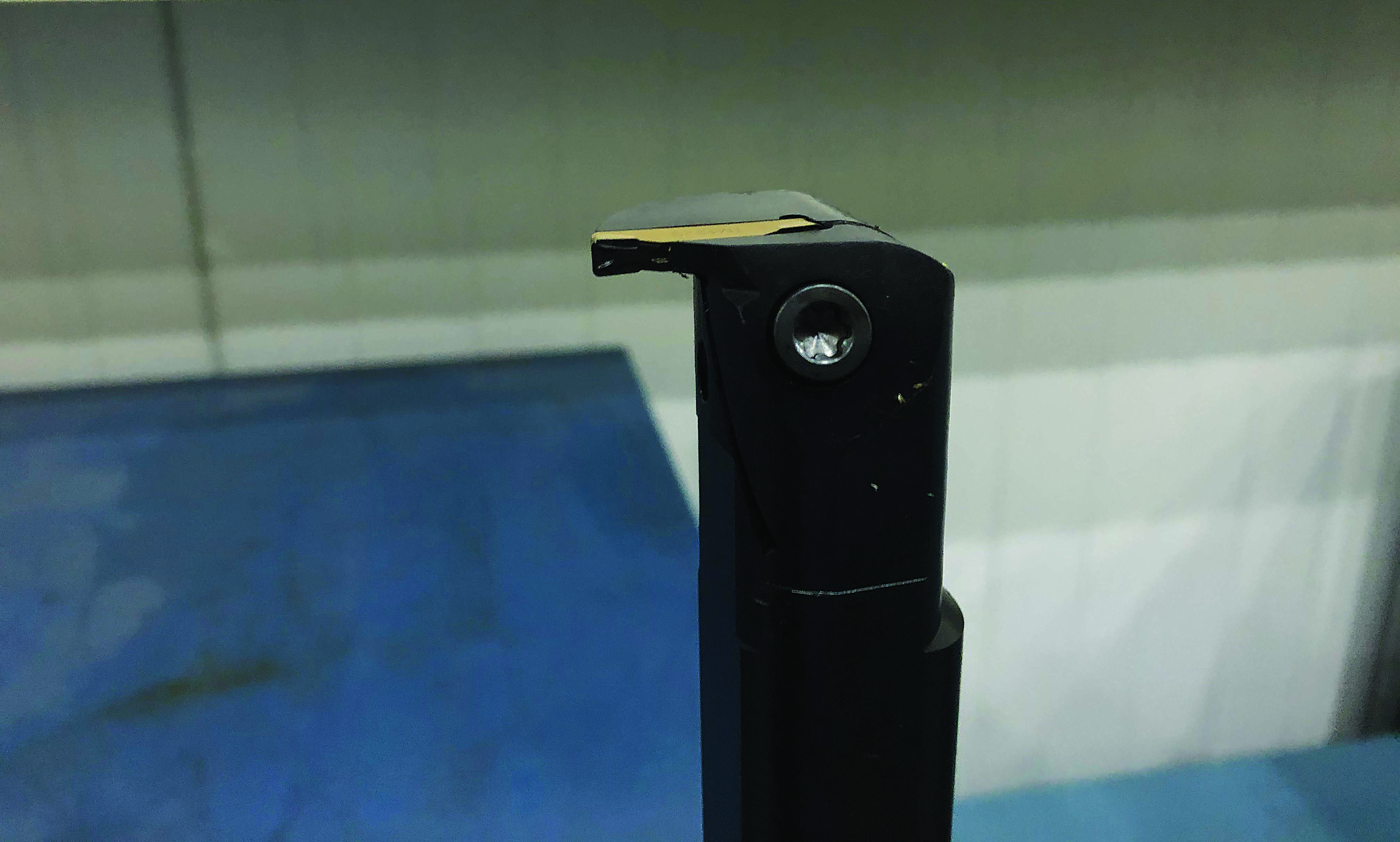
Used for internal grooves, this standard lathe grooving tool (right) is from a catalog. Mitsubishi Hitachi Power Systems Americas has used the tool in milling machines for hot jobs. Image courtesy of C. Tate

Lesson one. Buy a good grooving tool from a company that knows what it is doing. For manual machines, that frequently means purchasing a parting blade. Parting blades are made of high-speed steel and ground with proper clearances, so a tool does not rub the sides, which is the most common problem with hand-ground tools. Parting blades are available in many sizes and can be modified easily for special purposes.

Unfortunately, HSS tools do not always work well with hard or abrasive materials, which I discovered while machining cast-iron parts. Carbide grooving tools become a necessity with difficult-to-machine materials and bring their own challenges, especially on conventional machines. Carbide is significantly harder and more wear-resistant than HSS but very brittle and not as forgiving. Carbide tends to chip and break if not used properly. I learned this while feeding a carbide grooving tool by hand on cast-iron parts. That is lesson two.

Lesson two. Use a light feed rate, and let the machine feed the tool. Only hand-feed at the end if necessary.

Lesson three. When cutting grooves on a lathe, make sure that the grooving tool is on center or slightly below. Turning and facing tools can tolerate being above centerline, and small errors are often unnoticeable. But a grooving tool above centerline provides hours of aggravation as the part tries to climb up on the tool, the cutting edge continually is rubbed off or half a day is spent gingerly coaxing a piece of broken tool out of a shaft that is 99% complete.

I thought that grooving would be simple after we purchased a shiny new CNC turning center with a control that had canned grooving cycles. That is lesson four.

Lesson four. A CNC does not eliminate grooving challenges. Computer-controlled machines offer limitless combinations of cutting speeds, feed rates and cutting paths, which make grooving easier. But CNC turning centers separate a machinist and his or her senses from a tool and the work. Tool turrets are usually behind the work, and tools frequently are run with inserts toward the bottom of a machine. So it can be difficult for a machinist to see what is happening. Being able to read the chips and view the way a tool behaves is important to get the best cutting parameters, and CNC machines might make this hard. Many people never imagine that a tool turret on an expensive turning center would be off-center, but it is extremely common. When a turret is not set on center, a machinist may have to shim tools, modify holders or, worst-case scenario, adjust the turret.

Lesson five. Face grooving can be difficult, and success requires having the proper tools. I learned this while machining very deep face grooves in pump impellers. My first attempts were made with tools we had ground at my shop. (I was still in the process of learning lesson one.) Progress came when we purchased an indexable tool with carbide inserts that was made specifically for face grooves. A face grooving tool is made with a curved shape, so the heel of the tool does not rub the curved groove. Each tool is limited to a range of diameters, which means that one tool cannot be used on all face grooves. If tools are used for diameters outside their design limits, they rub and damage a part. I also realized that face grooving tools with clamps held in place with a screw are much better than the other styles in which the insert is pressed into a slot.


This face grooving tool is used for very large-diameter grooves. The curved blade creates clearance between a tool and part. Image courtesy of C. Tate

Lesson six. Not every cutting tool manufacturer can make special grooving tools. Grooves are common on power generation equipment like blade rings. These grooves are known as hook-fits, and they are used to hold smaller components in place. Hook-fit geometry is the same as a face groove, but hook-fits are made in areas where a normal face groove tool does not fit. Many grooving tool manufacturers are in the market. Most make excellent stock tools for grooving, but only a few are good at making special tools.

Machinists cannot see the tool tip when machining a hook-fit, so they do not know if there is a tool rub before the groove is done. Hook-fit tools must have perfect geometry so there is no question they will work properly. We tried several cutting tool manufacturers before finding a company that had the experience needed to make small quantities of special holders and inserts. We now use the supplier for all our special grooving tools.

Lesson seven. If it isn’t broken, don’t fix it. I learned to propagate results across different parts and avoid deviating from successful tools and techniques. In an era of continuous improvement, it can be difficult to watch a machining process that seems slow or uses expensive inserts without wanting to change it. After many failed attempts at enhancement, I recognized that a process making a satisfying part may not need improvement.

Grooving can be hard. For some of us, the lessons are painful. I found that the best outcomes came when I engaged cutting tool experts and explored options at trade shows. Being open to experimentation and making time to test are also important for developing good processes.    


Related Glossary Terms

  • abrasive

    abrasive

    Substance used for grinding, honing, lapping, superfinishing and polishing. Examples include garnet, emery, corundum, silicon carbide, cubic boron nitride and diamond in various grit sizes.

  • centers

    centers

    Cone-shaped pins that support a workpiece by one or two ends during machining. The centers fit into holes drilled in the workpiece ends. Centers that turn with the workpiece are called “live” centers; those that do not are called “dead” centers.

  • clearance

    clearance

    Space provided behind a tool’s land or relief to prevent rubbing and subsequent premature deterioration of the tool. See land; relief.

  • computer numerical control ( CNC)

    computer numerical control ( CNC)

    Microprocessor-based controller dedicated to a machine tool that permits the creation or modification of parts. Programmed numerical control activates the machine’s servos and spindle drives and controls the various machining operations. See DNC, direct numerical control; NC, numerical control.

  • feed

    feed

    Rate of change of position of the tool as a whole, relative to the workpiece while cutting.

  • gang cutting ( milling)

    gang cutting ( milling)

    Machining with several cutters mounted on a single arbor, generally for simultaneous cutting.

  • grinding

    grinding

    Machining operation in which material is removed from the workpiece by a powered abrasive wheel, stone, belt, paste, sheet, compound, slurry, etc. Takes various forms: surface grinding (creates flat and/or squared surfaces); cylindrical grinding (for external cylindrical and tapered shapes, fillets, undercuts, etc.); centerless grinding; chamfering; thread and form grinding; tool and cutter grinding; offhand grinding; lapping and polishing (grinding with extremely fine grits to create ultrasmooth surfaces); honing; and disc grinding.

  • grooving

    grooving

    Machining grooves and shallow channels. Example: grooving ball-bearing raceways. Typically performed by tools that are capable of light cuts at high feed rates. Imparts high-quality finish.

  • high-speed steels ( HSS)

    high-speed steels ( HSS)

    Available in two major types: tungsten high-speed steels (designated by letter T having tungsten as the principal alloying element) and molybdenum high-speed steels (designated by letter M having molybdenum as the principal alloying element). The type T high-speed steels containing cobalt have higher wear resistance and greater red (hot) hardness, withstanding cutting temperature up to 1,100º F (590º C). The type T steels are used to fabricate metalcutting tools (milling cutters, drills, reamers and taps), woodworking tools, various types of punches and dies, ball and roller bearings. The type M steels are used for cutting tools and various types of dies.

  • lathe

    lathe

    Turning machine capable of sawing, milling, grinding, gear-cutting, drilling, reaming, boring, threading, facing, chamfering, grooving, knurling, spinning, parting, necking, taper-cutting, and cam- and eccentric-cutting, as well as step- and straight-turning. Comes in a variety of forms, ranging from manual to semiautomatic to fully automatic, with major types being engine lathes, turning and contouring lathes, turret lathes and numerical-control lathes. The engine lathe consists of a headstock and spindle, tailstock, bed, carriage (complete with apron) and cross slides. Features include gear- (speed) and feed-selector levers, toolpost, compound rest, lead screw and reversing lead screw, threading dial and rapid-traverse lever. Special lathe types include through-the-spindle, camshaft and crankshaft, brake drum and rotor, spinning and gun-barrel machines. Toolroom and bench lathes are used for precision work; the former for tool-and-die work and similar tasks, the latter for small workpieces (instruments, watches), normally without a power feed. Models are typically designated according to their “swing,” or the largest-diameter workpiece that can be rotated; bed length, or the distance between centers; and horsepower generated. See turning machine.

  • milling

    milling

    Machining operation in which metal or other material is removed by applying power to a rotating cutter. In vertical milling, the cutting tool is mounted vertically on the spindle. In horizontal milling, the cutting tool is mounted horizontally, either directly on the spindle or on an arbor. Horizontal milling is further broken down into conventional milling, where the cutter rotates opposite the direction of feed, or “up” into the workpiece; and climb milling, where the cutter rotates in the direction of feed, or “down” into the workpiece. Milling operations include plane or surface milling, endmilling, facemilling, angle milling, form milling and profiling.

  • offhand grinding

    offhand grinding

    Hand-feeding a workpiece into a bench grinder. Usually utilized in the shop to resharpen tools. Attachments or other mechanical devices are required for increased efficiency and accuracy. See grinding.

  • parting

    parting

    When used in lathe or screw-machine operations, this process separates a completed part from chuck-held or collet-fed stock by means of a very narrow, flat-end cutting, or parting, tool.

  • turning

    turning

    Workpiece is held in a chuck, mounted on a face plate or secured between centers and rotated while a cutting tool, normally a single-point tool, is fed into it along its periphery or across its end or face. Takes the form of straight turning (cutting along the periphery of the workpiece); taper turning (creating a taper); step turning (turning different-size diameters on the same work); chamfering (beveling an edge or shoulder); facing (cutting on an end); turning threads (usually external but can be internal); roughing (high-volume metal removal); and finishing (final light cuts). Performed on lathes, turning centers, chucking machines, automatic screw machines and similar machines.