An examination of the grinding process through the lens of an electron microscope.
A picture is worth a thousand words, and that maxim holds true for grinding. The interactions between the abrasive grit and the workpiece occur at a microscopic level and can be hard to visualize. When I give my “High Intensity Grinding Course,” I’ll explain a subject for 5 minutes and watch attendees eyes start to glaze over. But when I flash a photo on the screen—Boom!—I see the “aha” in their eyes as they instantly form a mental picture of what I’m talking about.
Over the years, I’ve taken and collected hundreds of electron-microscope photos of grinding wheels, swarf, workpieces, dressing tools and just about everything else related to grinding. I’ve selected 22 of the best and assembled them here, presented with descriptions of the photos and interesting facts or trivia about grinding.
Courtesy of Niagara Cutter
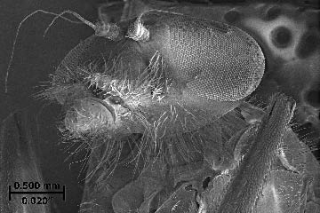
Figure 1: The head of a housefly. The hairs on the fly’s legs are 3μm thick, about the same thickness as a chip produced when grinding hardened steel. The fly’s eyes are each 0.700mm in diameter, about the same size as a 24-mesh abrasive grit.
Courtesy of J. Badger
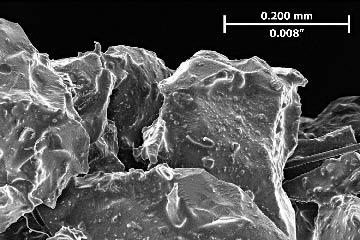
Figure 2: Sharp grits in a freshly dressed, 80-mesh, vitrified-bond aluminum-oxide grinding wheel. An 80-mesh, 16 "-dia., 2 "-wide, 2 "-bore wheel contains about one billion abrasive grits.
Courtesy of J. Badger
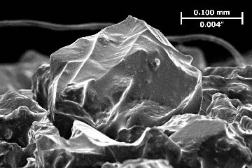
Figure 3: A single, 80-mesh Al2O3 grit in a freshly dressed vitrified-bond grinding wheel. A grit in a 16 " wheel running at 3,000 rpm taking a 0.001 " DOC is in contact with the workpiece 0.00008 seconds, or 0.08 milliseconds.
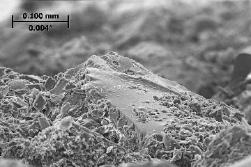
Courtesy of J. Badger
Figure 4: A dull grit in a worn, 46-mesh, vitrified-bond, N-grade, Al2O3 grinding wheel. Wheel dulling causes increased heat generation and grinding burn, increased normal forces and chatter and a finer surface finish.
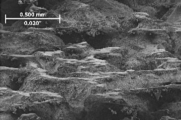
Courtesy of J. Badger
Figure 5: Dull grits in a worn, 46-mesh, vitrified-bond, N-grade, Al2O3 grinding wheel. This wheel was excessively dull, and the wear flats were visible to the naked eye. This N-grade wheel was “too hard,” meaning it had too much bond material and dull grits did not break out of the bond.
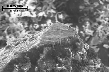
Courtesy of J. Badger
Figure 6: The tip of a microfracturing ceramic grit in a worn, 46-mesh, vitrified-bond, Al2O3 Norton-SG wheel after grinding hardened steel. This grit has done a lot of work, but it is not dull. Because it is a microfracturing grit, the tip of the grit remained sharp, enabling it to cut material efficiently.
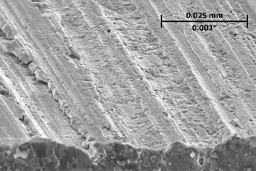
Courtesy of J. Badger
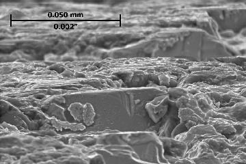
Figure 7: A ground and hardened steel surface. At the grit/workpiece interface there are three possible interactions: rubbing, side and front plowing and chip formation. Side plowing creates grinding scratches. This image shows plowing that caused the material to fold onto itself.
Courtesy of J. Badger
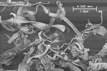
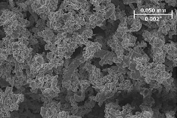
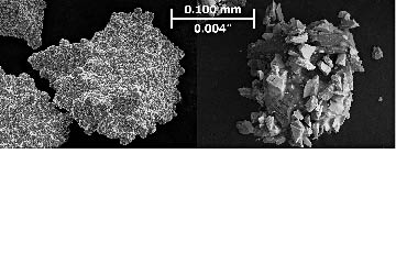
Figure 8: Swarf from grinding highly alloyed conventional HSS. Like turning and milling, grinding is a chip-formation process. However, the chips are thin and irregularly shaped. The swarf produced from grinding a standard ¼ "-dia., 4 "-long drill contains about 100 million individual chips.
Courtesy of J. Badger
Figure 9: A worn electroplated diamond wheel for grinding tungsten-carbide dies. This wheel was at the end of its life, but not wheel dulling is visible. The wheel experienced a large amount of grit fracture and bond fracture, and the cutting-point density increased to such a degree that the grits no longer effectively penetrated the workpiece.
Courtesy of J. Badger
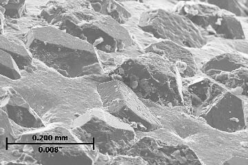
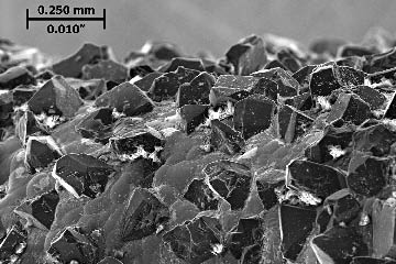
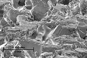
Figure 10: Swarf from grinding a tungsten-carbide workpiece with a resin-bond diamond wheel. Even grinding carbide, or “hard metal,” is a chip-formation process. However, because of carbide’s higher hardness and lower ductility compared to steel, the chips are shorter and blockier. Almost all grinding operations form chips. The exception is ceramic material, which has such low ductility that the material-removal mechanism isn’t chip formation but rather brittle fracture. Ceramic material is removed when cracks form below the surface followed by the “beating out” of chunks of hard ceramic material above the cracks.
Courtesy of J. Badger
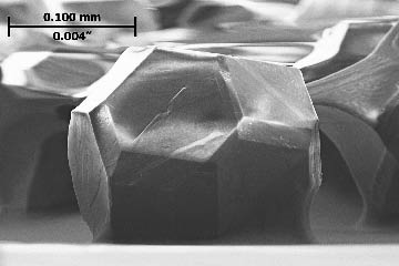
Figure 11: An 80/100-mesh diamond grit. Diamond and, in particular, cubic-boron-nitride abrasives can be manufactured in various geometries, from angular to blocky. This enables selection of geometries suited to particular grinding operations. The geometry shown is a truncated octahedron and is “blocky.” Therefore, it is suitable for grinding operations requiring high material-removal rates.
Courtesy of Niagara Cutter
Figure 12: A worn electroplated CBN grinding wheel. Because electroplated wheels are not dressed, distribution of grit heights is random. This means that initially only the very highest grits are in contact with the workpiece, resulting in low grinding forces, low heat generation and a rough surface finish. As the wheel “closes down,” the surface finish becomes finer and grinding power and heat generation both increase.
Courtesy of J. Badger
Figure 13: A worn, 140/170-mesh, resin-bond CBN wheel. Resin-bond wheels have little natural porosity. Here, only two grits can be seen poking above the bond material. “Sticking” the wheel clears some of the bond material, providing some porosity, but the wheel still has much less porosity than an electroplated or vitrified-bond wheel. As a result, cooling is more of a challenge and the wheels are more prone to mechanical loading.
Courtesy of J. Badger
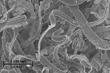
Figure 14: Swarf from using an Al2O3 wheel to continuous-dress grind a nickel-base alloy for making a turbine blade. Nickel-base alloys are very ductile, making the chips long and stringy.
Courtesy of J. Badger
Figure 15: Diamonds in a worn rotary diamond disc. Some of the individual diamonds, about 1mm in diameter, have broken out of the binder material, which leads to dressing tool failure.
Courtesy of J. Badger
Figure 16: Mechanical loading in a resin-bond CBN wheel after grinding hardened steel. (CBN grits are black, the bond material is gray and loaded steel is white.) CBN wheels are more prone to loading because of their slow rate of wear. With Al2O3, the wheel wears and/or is dressed away before loading can accumulate to levels where it inhibits the cutting action. With CBN, wear and dressing rates are low, so loading has time to accumulate. In addition, resin-bond wheels are prone to loading because they have little porosity.
Courtesy of J. Badger
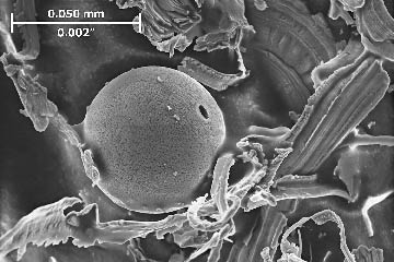
Figure 17: A melted globule of hardened steel amongst grinding chips. The melting point of iron is 2,800° F (1,540° C). This temperature is rarely if ever reached in grinding. However, as chips fly off the grinding wheel, they oxidize in the atmosphere. This is an exothermic reaction, meaning it gives off heat. This is what causes grinding sparks and, in this case, melting of the steel into a globule. No sparks or melted globules result during grinding tests performed in an inert nitrogen atmosphere.
Courtesy of J. Badger
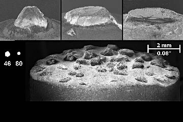
Figure 18: Clockwise from top left is a new single-point diamond, a worn single-point diamond, a very dull single-point diamond and a worn diamond cluster. Single-point diamonds are versatile. However, if they are not rotated they become dull, leading to a dull wheel. The sizes of 46-mesh and 80-mesh grits are shown on the same scale, giving an indication of how a dull diamond will dull an abrasive grit. One solution is to switch to a diamond cluster, which provides a more consistent result. However, because it is wider, the diamond traverse speed must be increased by at least a factor of four. Also, clusters are not as suitable for intricate geometries and small radii as single-point diamonds.
Courtesy of J. Badger
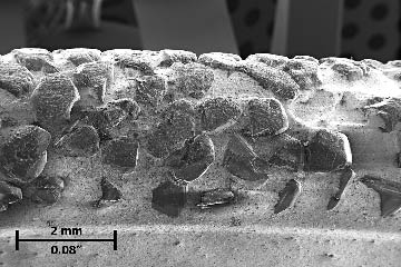
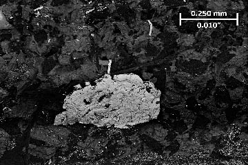
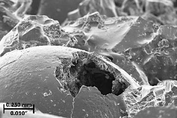
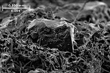
Figure 19: A broken hollow sphere in a worn, 30-mesh, vitrified-bond, induced-porosity Al2O3 grinding wheel. These “bubble alumina” hollow spheres give a wheel “ping-pong-ball porosity.” However, these spheres must be broken by the grinding or dressing operation and do not give the wheel “contiguous” porosity where coolant can flow from pore to pore. Therefore, ping-pong-ball porosity is not very effective.
Courtesy of J. Badger
Figure 20: Mechanical loading in a vitrified-bond Al2O3 wheel. Loading can be divided into two types: mechanical and chemical. Mechanical loading is when the chips become embedded in the porosity of the wheel. Chemical loading is when the workpiece chemically reacts with the abrasive grits and adheres to them.
One way to significantly reduce mechanical loading is to fill the pores of the wheel with high-velocity coolant.
Courtesy of J. Badger
Figure 21: Chemical loading in a 120-mesh, vitrified-bond Al2O3 wheel. Many strange chemical reactions occur between the grit and the workpiece. In this case, Al2O3 reacts with the thin layer of iron-oxide that forms immediately on the workpiece surface. It also reacts vigorously with the chromium-oxides that form in steels with chromium. What’s more, Al2O3 adheres to the virgin steel in the workpiece.
Courtesy of Winterthur
Figure 22: Coated superabrasive grits. Diamond and CBN grits don’t adhere well to a resin or metal bond. Therefore, a coating is used. The grit adheres to the coating, the coating adheres to the bond and therefore coated grits are held more firmly in the wheel. CTE
About the Author: Dr. Jeffrey Badger is an independent grinding consultant. His Web site is www.TheGrindingDoc.com.
Related Glossary Terms
- abrasive
abrasive
Substance used for grinding, honing, lapping, superfinishing and polishing. Examples include garnet, emery, corundum, silicon carbide, cubic boron nitride and diamond in various grit sizes.
- alloys
alloys
Substances having metallic properties and being composed of two or more chemical elements of which at least one is a metal.
- brittle fracture
brittle fracture
Separation of a solid accompanied by little or no macroscopic plastic deformation. Typically, brittle fracture occurs by rapid crack propagation with less expenditure of energy than for ductile fracture.
- chatter
chatter
Condition of vibration involving the machine, workpiece and cutting tool. Once this condition arises, it is often self-sustaining until the problem is corrected. Chatter can be identified when lines or grooves appear at regular intervals in the workpiece. These lines or grooves are caused by the teeth of the cutter as they vibrate in and out of the workpiece and their spacing depends on the frequency of vibration.
- coolant
coolant
Fluid that reduces temperature buildup at the tool/workpiece interface during machining. Normally takes the form of a liquid such as soluble or chemical mixtures (semisynthetic, synthetic) but can be pressurized air or other gas. Because of water’s ability to absorb great quantities of heat, it is widely used as a coolant and vehicle for various cutting compounds, with the water-to-compound ratio varying with the machining task. See cutting fluid; semisynthetic cutting fluid; soluble-oil cutting fluid; synthetic cutting fluid.
- cubic boron nitride ( CBN)
cubic boron nitride ( CBN)
Crystal manufactured from boron nitride under high pressure and temperature. Used to cut hard-to-machine ferrous and nickel-base materials up to 70 HRC. Second hardest material after diamond. See superabrasive tools.
- dressing
dressing
Removal of undesirable materials from “loaded” grinding wheels using a single- or multi-point diamond or other tool. The process also exposes unused, sharp abrasive points. See loading; truing.
- ductility
ductility
Ability of a material to be bent, formed or stretched without rupturing. Measured by elongation or reduction of area in a tensile test or by other means.
- flash
flash
Thin web or film of metal on a casting that occurs at die partings and around air vents and movable cores. This excess metal is due to necessary working and operating clearances in a die. Flash also is the excess material squeezed out of the cavity as a compression mold closes or as pressure is applied to the cavity.
- gang cutting ( milling)
gang cutting ( milling)
Machining with several cutters mounted on a single arbor, generally for simultaneous cutting.
- grinding
grinding
Machining operation in which material is removed from the workpiece by a powered abrasive wheel, stone, belt, paste, sheet, compound, slurry, etc. Takes various forms: surface grinding (creates flat and/or squared surfaces); cylindrical grinding (for external cylindrical and tapered shapes, fillets, undercuts, etc.); centerless grinding; chamfering; thread and form grinding; tool and cutter grinding; offhand grinding; lapping and polishing (grinding with extremely fine grits to create ultrasmooth surfaces); honing; and disc grinding.
- grinding wheel
grinding wheel
Wheel formed from abrasive material mixed in a suitable matrix. Takes a variety of shapes but falls into two basic categories: one that cuts on its periphery, as in reciprocating grinding, and one that cuts on its side or face, as in tool and cutter grinding.
- hardness
hardness
Hardness is a measure of the resistance of a material to surface indentation or abrasion. There is no absolute scale for hardness. In order to express hardness quantitatively, each type of test has its own scale, which defines hardness. Indentation hardness obtained through static methods is measured by Brinell, Rockwell, Vickers and Knoop tests. Hardness without indentation is measured by a dynamic method, known as the Scleroscope test.
- high-speed steels ( HSS)
high-speed steels ( HSS)
Available in two major types: tungsten high-speed steels (designated by letter T having tungsten as the principal alloying element) and molybdenum high-speed steels (designated by letter M having molybdenum as the principal alloying element). The type T high-speed steels containing cobalt have higher wear resistance and greater red (hot) hardness, withstanding cutting temperature up to 1,100º F (590º C). The type T steels are used to fabricate metalcutting tools (milling cutters, drills, reamers and taps), woodworking tools, various types of punches and dies, ball and roller bearings. The type M steels are used for cutting tools and various types of dies.
- milling
milling
Machining operation in which metal or other material is removed by applying power to a rotating cutter. In vertical milling, the cutting tool is mounted vertically on the spindle. In horizontal milling, the cutting tool is mounted horizontally, either directly on the spindle or on an arbor. Horizontal milling is further broken down into conventional milling, where the cutter rotates opposite the direction of feed, or “up” into the workpiece; and climb milling, where the cutter rotates in the direction of feed, or “down” into the workpiece. Milling operations include plane or surface milling, endmilling, facemilling, angle milling, form milling and profiling.
- swarf
swarf
Metal fines and grinding wheel particles generated during grinding.
- turning
turning
Workpiece is held in a chuck, mounted on a face plate or secured between centers and rotated while a cutting tool, normally a single-point tool, is fed into it along its periphery or across its end or face. Takes the form of straight turning (cutting along the periphery of the workpiece); taper turning (creating a taper); step turning (turning different-size diameters on the same work); chamfering (beveling an edge or shoulder); facing (cutting on an end); turning threads (usually external but can be internal); roughing (high-volume metal removal); and finishing (final light cuts). Performed on lathes, turning centers, chucking machines, automatic screw machines and similar machines.
- web
web
On a rotating tool, the portion of the tool body that joins the lands. Web is thicker at the shank end, relative to the point end, providing maximum torsional strength.
Author

Jeffrey A. Badger, Ph.D., is an independent grinding expert. He will be giving his 3-day High Intensity Grinding Course from Sept. 26-28 in Columbia, S.C., hosted by S.L. Munson. Visit www.thegrindingdoc.com for details. He can be reached by phone at 512-934-1857 or via email at [email protected].