Dear Doc: We surface-grind lots of stock (1mm per side) off of large plates (1,000mm × 500mm). Two cross-feed options are on our machine: 1) gradual, where the bed cross-feeds at a constant velocity throughout the forward and backward strokes, and 2) incremental, where the bed cross-feeds rapidly at the end of each stroke. There’s a lot of debate about which is better. What’s your take?
The Doc replies: I’m not a fan of gradual cross-feed, and here’s why.
First, let’s start with the basics. You have a lot of stock to remove. Therefore, you should use nearly the entire wheel width for roughing. This is a common mistake: using only, say, 20% of the wheel. If the wheel is 50mm wide, use nearly all that 50mm. Let’s say 90%, or 45mm. It’s ridiculous not to use almost all your wheel even if you have limited motor power. So when you do incremental cross-feed, have that wheel move over 45mm after each forward stroke and back stroke.

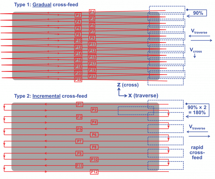
Different cross-feed styles for surface grinding. Image courtesy of J. Badger
You might wonder whether using more of the wheel will increase wheel wear and risk of burn. The answer is a resounding no. Wheel wear and burn risk depend mostly on the maximum Q-prime in a wheel. The equation is Q-prime = DOC in mm × traverse velocity in mm/sec. Notice that the cross-feed velocity (for the gradual cross-feed option), the cross-feed distance (for the incremental cross-feed option) or the wheel width isn’t part of this equation. Using 10%, 25%, 50% or 90% of your wheel width won’t change the risk of burn or the rate of wheel wear. The only thing it will do is increase the total spindle power and the risk of chatter. Assuming we’re OK on both of those, let’s use 90% of the wheel and reduce cycle time.
That brings us to the problem with gradual cross-feed: inefficiency. Let’s say the wheel finishes traversing the part on the forward stroke. The bed slows, stops and starts moving in the opposite direction for the reverse traverse. When the bed begins that reverse traverse, what fraction of the wheel is it using? Zero percent. That gradually becomes 10%, 20%, 30% and finally 90%, if that’s what you’ve set the velocity to achieve. It’s foolish to use only 0%, 10% and 20% of the wheel at the beginning of the stroke.
That’s why incremental cross-feed is better. When you get to the end of the stroke, you can move over almost the entire wheel and immediately use almost all the wheel. There’s no gradually decreasing overlap—just use the entire wheel.
This is illustrated in the figure shown here. Gradual cross-feed requires two strokes, forward and back, to get to 90% of the wheel. (Faster cross-feed velocity will cause you to overshoot and miss some of the workpiece.) Incremental cross-feed requires only one stroke. You can do the same job—with the same risk of burn and chatter—in half the number of strokes.
Also, if you use an Al2O3 wheel on a “soft” workpiece, such as steel, hardened steel, stainless steel or a nickel-base alloy, you can get even fancier. Here’s how: 1) Dress the wheel supersharp. 2) Remove almost all the material at deeper DOCs while cross-feeding 90% of the wheel width (the roughing cycle). 3) Dress the wheel semidull. 4) Remove the last 50μm using 12.5% of the wheel width with a smaller DOC and traverse velocity (the finishing cycle). Granted, after the roughing cycle the surface will be a mess, but who cares. We’ll clean that with the duller dress and smaller cross-feed distance.
Using this method, it’s unbelievable how much you can reduce cycle time. I’ve had people attend my three-day class, return to their shops the next morning, try it and email me that evening saying they cut cycle time from eight hours to one with no adverse effects.
Related Glossary Terms
- chatter
chatter
Condition of vibration involving the machine, workpiece and cutting tool. Once this condition arises, it is often self-sustaining until the problem is corrected. Chatter can be identified when lines or grooves appear at regular intervals in the workpiece. These lines or grooves are caused by the teeth of the cutter as they vibrate in and out of the workpiece and their spacing depends on the frequency of vibration.
- grinding
grinding
Machining operation in which material is removed from the workpiece by a powered abrasive wheel, stone, belt, paste, sheet, compound, slurry, etc. Takes various forms: surface grinding (creates flat and/or squared surfaces); cylindrical grinding (for external cylindrical and tapered shapes, fillets, undercuts, etc.); centerless grinding; chamfering; thread and form grinding; tool and cutter grinding; offhand grinding; lapping and polishing (grinding with extremely fine grits to create ultrasmooth surfaces); honing; and disc grinding.
- overshoot
overshoot
Deviation from nominal path caused by momentum carried over from previous step, as when a tool is rapidly traversed a considerable distance to begin a cut. Usually applies to CNC machining and is prevented if the control has the appropriate look-ahead capability. See look-ahead; undershoot.
- surface grinding
surface grinding
Machining of a flat, angled or contoured surface by passing a workpiece beneath a grinding wheel in a plane parallel to the grinding wheel spindle. See grinding.


