Getting to know the lead angle

Author Luke Pollock
Published
December 13, 2019 - 09:30am

Facemilling with indexable tools is common at shops. One does not have to look deeply into the offerings from indexable tool suppliers to realize that there are many tool designs. How to select the correct one for an application can be challenging. However, if the effects from the facemill’s main design features are understood, choosing a suitable cutter body becomes much easier.

One such feature is the lead angle of a tool. The lead angle is an angular dimension measured parallel to the cutting edge of the tool and to the face of the part being produced (Figure 1). The angle affects the way the tool performs, how it should be applied and how the finished part looks. Typical lead angles available in standard tools are 90°, 60°, 45° and 15°.


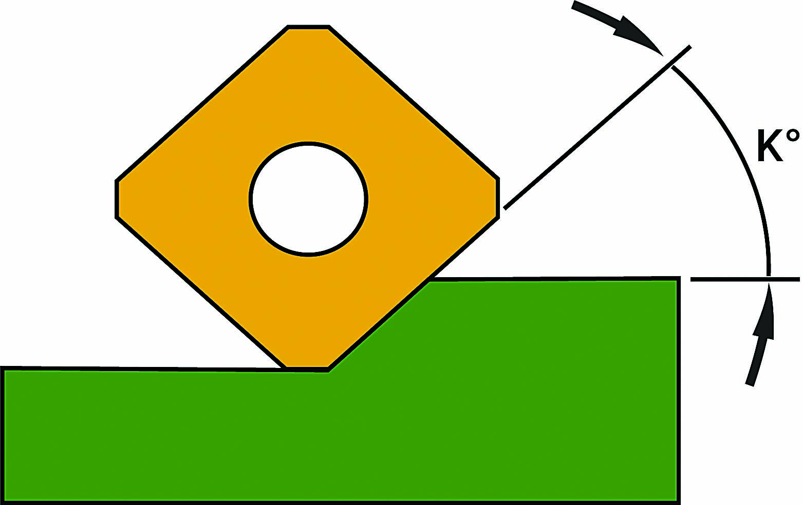
Figure 1: The lead angle of a facemill can have a big impact on the way it performs.

Calculations

It is worth trying to understand how a lead angle impacts the way that cutting forces are directed (Figure 2). The generated net cutting forces always react in the direction perpendicular to the cutting edge. Mathematically, to make it easier to comprehend these forces, they can be broken into two vectors: one in the horizontal direction and one in the vertical direction. 


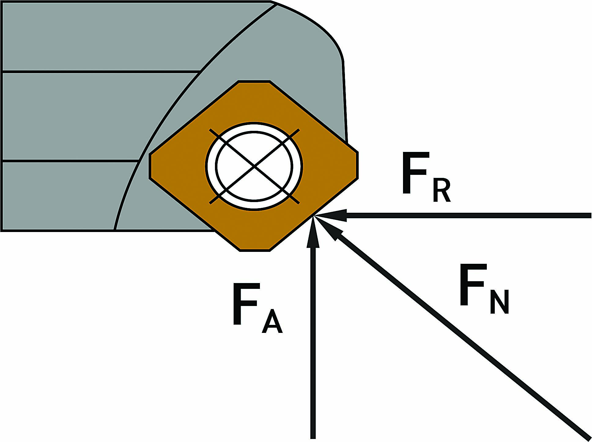
Figure 2: Net cutting force can be divided into axial and radial components.

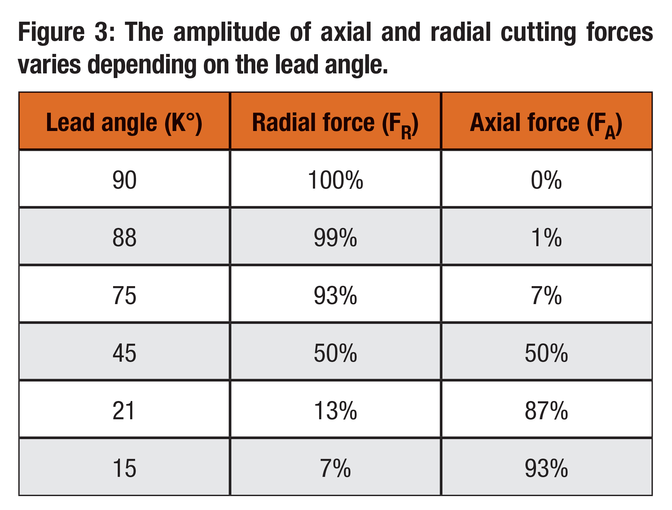
The amplitude of each vector shows where the larger of these two forces exists (Figure 3). Using a formula from basic trigonometry, how these forces should be divided can be calculated. Multiplying the net force (FN) by either the sine or cosine of the lead angle tells what percentage of the forces is acting vertically and what percentage of them is acting horizontally.

Horizontal forces, which act perpendicular to the tool axis, are less desirable than vertical forces. Think of it as trying to push the facemill off-center. Forces moving in this direction can cause deflection, chatter and spindle tilt, all resulting in poor tool life and part quality. Vertical forces are much more desirable because they are parallel to the tool axis. This means they are directed straight up in line to the spindle axis, which has the entire rigidity of the machine opposing these forces. The machine is better equipped to handle forces in this direction, so the operation does not lose stability.

Axial Chip Thinning

The lead angle is also involved with a phenomenon called axial chip thinning, which is a result of the lead angle geometry and the feed rate. When the lead angle is equal to 90°, physical chip thickness is equal to the advance per tooth programmed into the machine. Because chip thickness is measured perpendicular to the lead angle, as the lead angle increases, chip thickness becomes thinner with the same advance per tooth (Figure 4). 


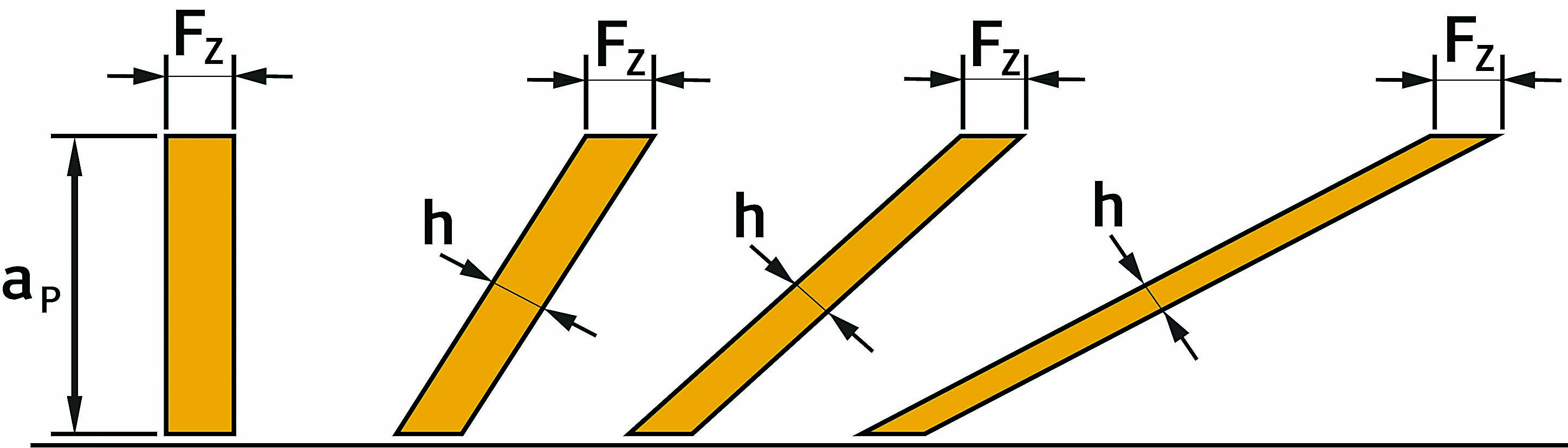
Figure 4: As the lead angle becomes smaller, the effects of axial chip thinning become greater.

Regardless of how much the chip thickness is influenced by chip thinning, chip thickness should adhere to the recommendation of the cutting tool manufacturer. This means increasing the advance per tooth (FZ) as the lead angle increases so the recommended chip thickness is maintained. If it becomes too small, the tool can rub and not actually cut the workpiece.

A second negative of not properly counteracting the effects of axial chip thinning relates to managing the heat produced when facemilling. If the chip becomes too small, it loses the ability to hold heat, which ideally should go into the chip and be carried away. When this heat transfer does not happen, the heat goes into the part or tool. Either is undesirable because that would hurt part quality or tool life.

Comparisons

Every choice brings advantages and disadvantages, so consider trade-offs among 90°, 45° and 15° facemills.

The biggest benefit of using a facemill with a 90° lead angle is that it can produce a square shoulder. (These tools sometimes are called shoulder mills.) Many times, particularly when finishing a part, the call is for a square shoulder. This could be not only at the bottom of a pocket but, if a taller wall is to be produced, by stepping down the cutter and taking multiple passes to produce the wall. This application would call for a true 90° lead angle. If it was not a true 90°, such as a facemill with a square insert, which typically can produce an 89.75° shoulder, it would not meet most finished part specifications. That small deviance would be visible in a tall shoulder.

The sacrifice is that 100% of the load would be in the axial direction, making chatter easy to generate. This limits the feed rate and explains why most 90° facemills have positive insert geometry to free up cutting forces. The lack of axial chip thinning restricts feeds and speeds as well.


A high-feed mill is a good choice for long reaches because it directs the majority of cutting forces up through the spindle.

It frequently has been said that every shop should have at least one 45° lead facemill because it evenly splits cutting forces, with 50% in the axial direction and 50% in the radial direction. Managing cutting forces this way provides stable, consistent cutting, allowing speeds and feeds to be maximized. The lead angle also furnishes good chip thinning. Because the actual chip is approximately 30% thinner, the feed rate must be increased by 30% to maintain the recommended chip load.

Not being able to produce a square shoulder in a finished part is the main disadvantage of this facemill, which is why it should be considered a roughing tool. Especially when preparing a part, an operation often calls for roughing material and has no shoulder requirement. In this case, it is much more efficient to use a 45° lead facemill to get higher material removal rates and a better balance of the cutting forces acting on the spindle.

Facemills with lead angles of 15° generally are considered high-feed mills. In other words, the application changes slightly from standard facemills. The lead angle is so extreme in this event that cutting forces and axial chip thinning become one-sided. Regarding cutting forces, 93% are in the axial direction, which is directed up through the spindle. This makes a 15° lead cutter quite stable even with long overhangs or when machining deep pockets. Only 7% of cutting forces are in the radial direction.

The term high-feed mill describes the way a facemill with a 15° lead angle needs to run. The increase in the required advance per tooth compared with a 90° facemill is about 93%, so it is common to see recommended cutting parameters in the range of 1.27 mm to 1.52 mm (0.05" to 0.06") advance per tooth. This generates high removal rates.

When parts are not clamped properly or have thin bottoms, cutting forces in the axial direction can have negative consequences. Remember the adage “For every action, there is an equal and opposite reaction”? Directing the majority of cutting forces into the spindle causes an opposite reaction in that the same forces push down on the part. So it has to be somewhat rigid and able to accept large cutting forces in the axial direction.

When an insert is tipped at an extreme 15° lead angle, it usually requires a very light DOC. The true DOC depends on the size of the insert. While this frequently is viewed as limiting, the intense feed rates can more than make up for the light DOCs, and the overall removal rates still can exceed that of a 90° facemill taking heavy DOCs at slower feeds and speeds.

Facemills come in different configurations. The varied designs are for specific intentions. Comprehending the reasons behind design characteristics helps an end user choose the correct tool for an application. 

The lead angle is a trait that greatly impacts the way a cutter performs and the appropriate applications for a tool. The angle affects the shoulder left in a part, the direction in which cutting forces are applied and the actual chip thickness produced. Understanding these effects aids with selecting a cutter body and maximizing productivity.    


Related Glossary Terms

  • chatter

    chatter

    Condition of vibration involving the machine, workpiece and cutting tool. Once this condition arises, it is often self-sustaining until the problem is corrected. Chatter can be identified when lines or grooves appear at regular intervals in the workpiece. These lines or grooves are caused by the teeth of the cutter as they vibrate in and out of the workpiece and their spacing depends on the frequency of vibration.

  • cutting force

    cutting force

    Engagement of a tool’s cutting edge with a workpiece generates a cutting force. Such a cutting force combines tangential, feed and radial forces, which can be measured by a dynamometer. Of the three cutting force components, tangential force is the greatest. Tangential force generates torque and accounts for more than 95 percent of the machining power. See dynamometer.

  • facemill

    facemill

    Milling cutter for cutting flat surfaces.

  • facemilling

    facemilling

    Form of milling that produces a flat surface generally at right angles to the rotating axis of a cutter having teeth or inserts both on its periphery and on its end face.

  • feed

    feed

    Rate of change of position of the tool as a whole, relative to the workpiece while cutting.

  • lead angle

    lead angle

    Angle between the side-cutting edge and the projected side of the tool shank or holder, which leads the cutting tool into the workpiece.

  • milling machine ( mill)

    milling machine ( mill)

    Runs endmills and arbor-mounted milling cutters. Features include a head with a spindle that drives the cutters; a column, knee and table that provide motion in the three Cartesian axes; and a base that supports the components and houses the cutting-fluid pump and reservoir. The work is mounted on the table and fed into the rotating cutter or endmill to accomplish the milling steps; vertical milling machines also feed endmills into the work by means of a spindle-mounted quill. Models range from small manual machines to big bed-type and duplex mills. All take one of three basic forms: vertical, horizontal or convertible horizontal/vertical. Vertical machines may be knee-type (the table is mounted on a knee that can be elevated) or bed-type (the table is securely supported and only moves horizontally). In general, horizontal machines are bigger and more powerful, while vertical machines are lighter but more versatile and easier to set up and operate.

  • parallel

    parallel

    Strip or block of precision-ground stock used to elevate a workpiece, while keeping it parallel to the worktable, to prevent cutter/table contact.

Author

Product Manager, Walter USA

Luke Pollock is product manager at Walter USA LLC, Waukesha, Wisconsin. For more information, call 800-945-5554 or visit www.walter-tools.com.