With hydraulic power workholding, the fundamental rules of fixturing apply, as well as the principles of hydraulics.
In a typical run of several parts, the most tedious and repetitive task is the job of positioning and clamping the workpieces. It’s a job an increasing number of shops are giving to hydraulic-power-workholding systems, which use hydraulically activated clamps and components.
Hydraulic workholding may not be suitable for every project, but for a large number of applications it can provide a cost-effective fixturing alternative. By letting hydraulics do the work, many shops have been able to increase load/unload times, reduce workpiece vibration, implement automated fixturing, increase machining speeds and feeds, lengthen tool life, and precisely control workholding forces. For the operators who previously positioned and clamped workpieces by hand, hydraulic power workholding has meant improved ergonomics and a decrease in the stresses that can lead to repetitive-motion injuries.
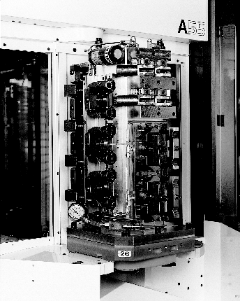
Figure 1: Hydraulic fixtures such as these have helped many shops achieve higher productivity and made working conditions safer.
To determine if your project will benefit from a hydraulic workholding system, you must carefully consider all of your project’s workholding needs. Some questions you should answer before designing the fixture include:
- How many operations are required?
- What machine will be used?
- What is the expected cycle time?
- How many parts will be run?
- How often will parts be run?
- How fast must the workpiece be changed?
The answers to these questions will help you calculate a cost/benefit ratio for the different clamping systems that might be used with the fixture. There are no hard and fast rules that dictate when to use a hydraulic workholding system, but wherever there is a critical need for fast cycle times and ease of operation, hydraulics might be called for.
Hydraulic Principles
As quick and simple as hydraulic workholding is to operate, it is not a system that can be thrown together without planning and forethought. At every step in the installation process, from choosing a system to installing the components and routing the hoses, the principles that govern both workholding and hydraulics must be considered.
A fundamental of hydraulics states that pressure applied to a confined fluid is transmitted equally in all directions. This principle allows the transmission of pressure through tubes and hoses to remotely located actuators, where that pressure is converted to usable force. This force is distributed equally to every component connected to the system. The simplicity of hydraulic workholding can be summed up in one small equation:
Force = Pressure x Area
To create and transfer pressure and hold workpieces, a hydraulic workholding system will incorporate an electrical or air-powered pump; controls, including a directional valve; and actuators, including clamps, cylinders, and work supports (Figure 1). The actuators, which locate and hold the part, are installed on the fixture. The controls can be located on the fixture, but typically they are mounted at the operator’s workstation. The pump is usually installed in a location that’s out of the way.
Making Choices
Early in the planning stage you must decide whether you will use single- or double-acting components. Single-acting components are actuated using hydraulic pressure, but hydraulic pressure is not needed to release them. Typically, these components are released when pressure is removed and a spring returns the actuator to its original position. This forces the hydraulic fluid back into the pump’s reservoir. A system using single-acting components is usually the most cost-effective, because each actuator needs only one pressure-source connection for operation.
Double-acting components use hydraulic pressure to close and to open again. Double-acting systems require double plumbing, using up more fixture space and adding to the cost. Despite this drawback, there are many good reasons to use double-acting systems. The compounded restrictions in complex or large circuit designs related to the diameter of the tubing, the length of the lines, or the number of fittings can slow the return of single-acting components. Double-acting components are not affected by these restrictions, because they use the redirected pressure from the pump to open. Double-acting components also are ideal for applications that require components to be both pushed and pulled or applications that use custom-designed attachments whose weight would retard the spring action of a single-acting component. A shop may choose double-acting clamps because it needs fast or precisely timed clamping and unclamping action. Double-acting clamps are often used in automated systems, because their fast, positive, predictable action can be coordinated with the rest of the system. The double-acting mechanism also allows users to monitor the status of the clamp by installing pressure switches in both the pressure and return lines that can signal the machine tool to shut down if pressure is lost.
Another choice to be made at the planning stage is the method that will be used to actuate the components. There are systems with varying degrees of automation available. The simplest systems use manually operated valves that require the operator to turn a handle to clamp and unclamp the fixture. At the other end of the spectrum are totally automated systems. In these systems, the machine tool’s controller can be programmed to control the clamping and unclamping functions while the workholding system’s electric solenoid valves open and close the components. Typically, M-codes are used in the part program to control these functions.
Plumbing Options
Tubing and hoses are used to connect all of the hydraulic workholding components and route pressure to the actuators. This plumbing is an essential part of the fixture. Decisions about which type and size of tubing and connectors to use and where to route the lines should be made early in the fixture-design process and not left as an afterthought.
The components can be conventionally mounted or manifold mounted. Because conventionally mounted components are readily available, conventional mounting will typically cost less than manifold mounting, which requires custom-designed components. Conventionally mounted components have threaded ports that accept fittings for tubing and hoses (Figure 2). Many different types of fittings are available, giving you several options for customizing your design.
Manifold-mounted components eliminate the need for external fittings, tubing, and hoses, because the fluid passages are machined directly into the fixture. Securing a hydraulic component to a fixture automatically makes the hydraulic connection (Figure 3). One of the most important benefits of manifold mounting is the fixture’s compact size. By eliminating the lines going to all the components, a shop can make maximum use of valuable fixture space. Manifold mounting also reduces the number of hydraulic connections, which results in fewer potential leak points and a cleaner, more professional-looking fixture.
Whether you use conventionally mounted or manifold-mounted components, the size and length of the plumbing lines you use to connect them to the pump and controls will have a significant impact on your fixture’s performance. The back pressure created by fittings, tubing, and hoses can slow the operation of your system, especially the return of single-acting components. Plumbing runs designed with larger diameter tubing and hoses and a minimal number of bends and fittings are less prone to this back pressure. Most systems in the North American market use 1/4" outer-diameter (OD) tubing and 1/4" or 3/16" inner-diameter (ID) hoses. When specifying flexible hoses and rigid tubing for the system, you must keep in mind that the two are sized differently. Hose is specified by its ID, while hydraulic tubing is usually specified by the OD.
The viscosity of the hydraulic fluid used also greatly affects back pressure. While the workholding-system manufacturer’s recommendation will almost always be suitable, occasionally a thinner fluid may be needed to reduce back-pressure problems.
Designing the Fixture
Typically, hydraulic components are used to either position or clamp the workpiece. Positioning components, which are typically cylinders, work by pushing the workpiece against solid positioning stops built into the fixture.
Clamping components hold the workpiece in position during machining. Unlike clamps, positioning components can be considered optional, depending on the workpiece, fixture design, and the level of operator involvement desired. A properly designed fixture that incorporates positioning components is easy to use. The operator simply places the workpiece into the fixture and operates the controls. The positioning components correctly orient the workpiece against the stops and hold it there while the clamps are sequenced to secure the part.
When a fixture fails to hold a part securely in the correct position, it may be the fault of the fixture design. Often, a shop will turn to hydraulic workholding to fix a problem it was having with a mechanical fixture. But if the mechanical fixture’s design flaws are copied when the new fixture is built, the shop will probably continue to have problems. The same basic workholding rules apply whether mechanical or hydraulic components are used. Simply adding hydraulics to an improperly designed system won’t help.
One of the most basic concepts of workholding is referred to as the 3-2-1 locating principle. This principle is based on the idea that to repeatedly locate (or reference) a workpiece, it must be oriented and positioned in three planes: x, y, and z. For example, picture a fixture holding the workpiece in place by gravity until it is clamped. At this stage it is only supported in the z-axis and is still free to rotate or slide in the x and y directions. Knowing that three points define a plane, it follows that, technically, the workpiece is being held in place in the z-axis at only three points regardless of its shape. To prevent rotation and to position the workpiece in the y direction, two stops are used. With the part contacting three stops in the z-axis and two stops in the y-axis, the only direction the part can move is in the x-axis. A single stop is all that is needed to prevent this motion. Thus, to prevent movement in all three planes you need only three primary (z-axis) locators, two secondary (y-axis) locators, and one tertiary (x-axis) locator (Figure 4). This is why this basic rule is called the "3-2-1 principle." These are the only stops required to locate a rigid part. Using more than these duplicates your effort and can affect repeatability from one part to the next.
When designing the solid stops for a fixture, it is usually best to locate them so that they directly resist the machining forces created in the feed direction. If solid stops are used to resist the cutting tool forces, the workholding clamps are needed only to hold the part in position. For this task, you can use smaller, less expensive clamps than the clamps you would need to resist cutting forces.
Clamps and cylinders are available with strokes that vary from 0.125" to more than 6.000". Your fixture design should never require the clamp or cylinder to be extended to its full stroke length. A fixture that requires only a partial extension of the component will have enough leeway to accept all tolerances and variations in the workpiece, workholding device, and fixture.
Your design must also take into account the hydraulic workholding components’ operating-pressure ranges. A good rule of thumb is to choose clamps and cylinders that will give you the forces you need at a pressure somewhere near the middle of their ranges. This will give you plenty of latitude to adjust the system’s pressure either up or down as needed to fine-tune the fixture. Even though it is sometimes necessary, operating at a low pressure does not make the most efficient use of the clamps and cylinders. When clamping-force requirements are well defined, the fixture can be designed to operate near the maximum pressure the system can generate. By using higher pressures to create more force at the clamp, you can hold the workpiece with smaller, less expensive clamps and cylinders. To operate at these higher pressures, make sure you specify only fittings that are rated for the maximum pressure that will be used in the application.
System Care and Maintenance
The single most important influence on the lifespan of a properly designed system is the cleanliness of the fluid. During assembly, you must make sure all fluid-carrying components are flushed with clean solvent and blown dry. Hydraulic tubing, which is oiled to prevent corrosion in shipping and storage, is notorious for the amount of dust and contaminants that collect inside the tubes before they are installed. If not removed, this debris will quickly damage seals and score precision-fit metal parts. The contamination will also clog passages in pumps and control valves.
After you have assembled your fixture, flush the entire system to remove any contamination created during assembly. Use only hydraulic fluid for this procedure, as solvents may become trapped in the system, contaminating the fluid. Keep the fluid in the system clean by changing it on a regular basis; a properly maintained system will need a change annually. Whenever you must disconnect or disassemble the system, be extremely careful to avoid introducing new contaminants.
Air trapped in the hydraulic system is the most common cause of erratic operation and slow return times. A typical way to bleed a system is to pressurize the circuit and carefully loosen a fitting just enough to let fluid escape. The trapped air will usually be flushed out with the fluid. With conventionally mounted components, the fittings that connect the lines to the components provide ideal bleeding locations. Since manifold mounting eliminates external fittings and lines, the fixture designer must consciously plan for system bleeding in the design.
Hydraulic workholding is fast becoming the preferred choice for workholding in many different machining arenas. Designers have a broad range of options available to build systems that precisely meet your application’s needs. With proper maintenance and a design that follows the principles of hydraulics and workholding, these fixtures can enhance productivity while providing many hours of service.
About the Author
Dann Rypka is the product and marketing manager for Hytec, Power Team Division of SPX Corp., Owatonna, MN.
Related Glossary Terms
- feed
feed
Rate of change of position of the tool as a whole, relative to the workpiece while cutting.
- fixture
fixture
Device, often made in-house, that holds a specific workpiece. See jig; modular fixturing.
- inner diameter ( ID)
inner diameter ( ID)
Dimension that defines the inside diameter of a cavity or hole. See OD, outer diameter.
- outer diameter ( OD)
outer diameter ( OD)
Dimension that defines the exterior diameter of a cylindrical or round part. See ID, inner diameter.