Get the Spin on Rotors
Get the Spin on Rotors
Effective use of rotary devices helps shops move forward.n
Indexers, dividing heads, spin jigs and many other rotary devices are common hardware in toolrooms and machine shops. Having the ability to accurately rotate a part through a circular path simplifies machining everything from keyways to bolt-hole circles.
In the not-so-distant past, having a rotary device for a CNC machine in your job shop set you apart from the competition. Today, the devices are almost ubiquitous. Being able to accurately position and interpolate in multiple axes and planes is now a necessity.
Unconventional Uses
Even those who are only moderately familiar with machining easily recognize the common uses of rotary tables and understand how rotary devices can improve efficiency in traditional machining operations. With a little creativity and some design skill, rotary devices can also be incorporated in less conventional ways to help drive continuous improvement and improve efficiency.
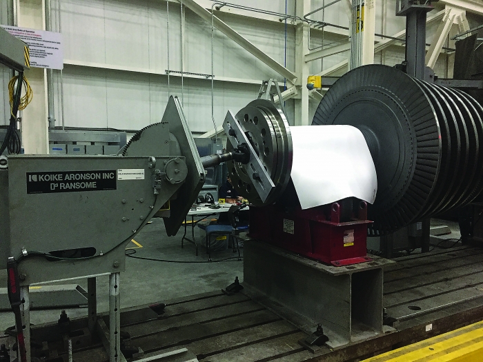
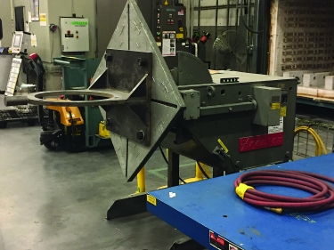
With a rotating weld positioner to drive a rotor on rollers, Mitsubishi Hitachi Power Systems Americas can use smaller, more cost-effective equipment for rotor repairs. Image courtesy of C. Tate
At Mitsubishi Hitachi Power Systems Americas, we build various components for the manufacture of gas turbines. Many of these are complex weldments that require the welder to manipulate the components through a range of positions. We use tables that rotate and tilt, allowing the necessary range of motion. That is what the positioners were designed to do—nothing unusual or creative.
It is said that necessity is the mother of invention, and that is true in our shop. After working with these welding positioners for a while, we began to realize they could be used to perform other tasks.
After welding is completed, our combustion baskets must be assembled before installation in the gas turbine. Baskets are heavy and cumbersome. Because assembly requires accessing multiple sides, several crane moves are required.
Crane moves, however, are not only slow but dangerous, placing assemblers and parts in risky situations. Although combustion baskets are robust, they have special protective coatings that are delicate and can be chipped easily. Each crane move provides an opportunity to damage the coatings or, worse, the assembler.
It was one of our assemblers who suggested we use a welding positioner to manipulate the part for assembly. As a result, we cut a few pieces with our waterjet, welded them together and bolted the fixture onto an old weld positioner. Now, we lift the basket into and out of only the fixture. All other manipulation takes place safely on the positioner.
Maintaining Rotors
Rotors are the heart of any turbine and, like all machines, require periodic maintenance. A significant part of our business is inspecting and repairing rotors. Steam turbine rotors are subject to harsh environments; it is common to find cracks and other defects that require repair by welding.
Steam turbine rotors are essentially a series of discs on a shaft. When a disc needs repair, we remove the bad section by turning it on a lathe and then building up the section via welding so it can be machined to the required geometry. Welding is done by placing the bad section under the torch and rotating the rotor while new material is added.
Small steam rotors can weigh 4,000 lbs. and be 6' long; large rotors can weigh 200,000 lbs. and be 50' long. This variation can make sizing equipment difficult and prohibitively expensive. Obviously, a rotary positioner sized for a 4,000-lb. rotor is not large enough to handle one that weighs 100 tons. Likewise, a positioner that can take 100 tons is too large for a small rotor.
An assembly fixture built from an old assembly table improved safety and productivity. Image courtesy of C. Tate.
We overcome this problem by placing the rotor on a set of rollers and driving it with a rotary positioner connected with a drive shaft that has universal joints—like the drive shaft on a car. This way, we do not need to support the weight of the rotor with the positioner. Instead, the positioner needs to be large enough only to drive the rotor in the rollers. Surprisingly, this can be achieved with a relatively small positioner.
It is easy to recognize the advantage of having a machine that runs continuously. Some of the more familiar devices that aid continuous operation are robots, bar feeders and machines with multiple pallets. One ingenious way I have seen continuous operations supported was with the use of a rotary table.
Small shops don't often have the resources to purchase complex hardware to support continuous operation. This was the case in a small shop I visited. The owner had mounted a rotary table on one of his vertical machining centers, and on the rotary table he had placed a fixture that held multiple parts. Each time a part was completed, the table would rotate to the next position and continue working while a machinist would remove a completed part and replace it with a new workpiece. Having multiple parts mounted on a rotary device is not uncommon, but usually the machine has to stop from time to time so parts can be loaded and unloaded. In this case, the VMC never stopped, which improved throughput and allowed the machinists to perform other tasks.
The use of rotary devices is not new, and the applications described here may not seem original to some metalworking professionals. But in the modern world of the industrial internet of things and apps, we can easily lose the ability to be creative. Talking about alternative uses and examining creative applications can help drive efficient problem-solving in a shop.