The world of a CAM programmer may seem straightforward and orderly. Programmers build toolpath strategies in logical sequences, select cutters from a library and calculate and simulate results.
But there are complex challenges when moving from the sterile programming office to the shop floor. The theoretical process becomes real.
About 10 years ago, the goals of CAM technology were quite basic. Everything fell into two important categories: Improve the experience of either the programmer or those on the shop floor. Software that provided faster calculation times, an easier and more-organized user interface and new strategies to simplify programming aided the programmer. Shop floor personnel, however, sought software that generated toolpaths able to eliminate or minimize collisions and that enhanced toolpath efficiency to extend tool life.
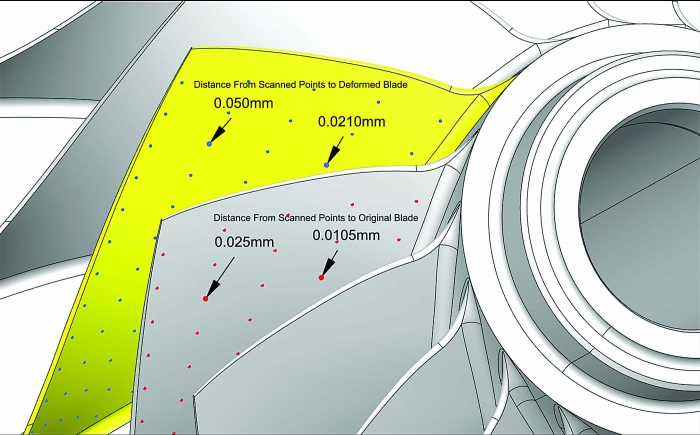
A compressor impeller shows deviation after first-article inspection. Image courtesy of Open Mind Technologies USA.
Reducing engineering costs or making parts faster and with higher quality is certainly a positive development. But a shop’s overarching goal is to make a part that is accepted by the customer. That requires controlling the many variables that enter the scene when the programming world meets the shop floor.
Machine tools may be aging, for instance, or may have experienced a spindle crash that left them out of factory alignment. The shop environment, such as room temperature, might not be controlled. Also, practical tolerance issues exist. Tools may have been ground or re-ground incorrectly. Some toolholders have runout. Machine spindles might grow when running under load. Tool lengths can vary.
Then consider the realities of machining: A thin-walled surface or a long cutter may deflect, or a worn cutter may not behave predictably.
Modeling these variables can be useful to producing an accurate part. In a sense, it is akin to making a part wrong to ultimately make it right. People attempt to model these situations, whether through examining spindle warm-up each morning, probing to check tool length or updating the controller offset tables. But the reality is that making a part to meet all tolerances and objectives is not easy.
To achieve total part quality, additional modeling is needed. This modeling is available with advanced CAM software. Although specific software compensations are not provided for each of the previously mentioned process issues, the best solution is to target the totality of process issues so the workpiece meets the required quality standards.
The following examples begin to create a paradigm for how to make a better part. In one case, a deformed model was programmed and machined. In the other, the toolpath was programmed intentionally with sophisticated offsets and blending algorithms to improve part quality.
Production example: Turbomachinery compressor impellers are complex parts that must be machined to a tight positional tolerance. These components operate as high-speed rotational devices. In addition, blade failure can cause instant damage and even loss of life. Therefore, the manufacturing process must be consistent for all blades.
Typically, a centrifugal compressor has a long leading-edge surface and, compared with the hub, thinner sections near the shroud (outer contour), which leads to machining challenges.
Industrial compressors are usually built to spec for each application, but aero-engine components are manufactured in production quantities via a defined process to achieve the needed quality standards.
The typical way to set up a consistent production process for these compressors is to make first-article components and measure impeller blade surfaces. Because of machining challenges caused by blade deflection and other previously mentioned process issues, the first-article component is typically not made within dimensional tolerances. For example, the area near the leading-edge shroud may be oversized by 0.004" (0.1mm), but areas near the hub and trailing edge may be correct or close to nominal size. Therefore, the deviation map is not uniform.
The CAD model is then deformed according to the deviation map to compensate for deflection and other errors. Because the deviation is not uniform, the deformation is a complex set of offsets. The deformed model is used for programming subsequent units. Deflection and other errors create an oversized part, relative to the deformed model. However, the machining deflections and process issues on the deformed model result in an in-tolerance part compared with the actual part model.
Mold and die making example: The requirements of mold and die makers are considerably different from those of manufacturers of aero-engine parts. In moldmaking applications, specific dimensions near fillets are not usually critical to part performance, but surface finish and blends in areas where cutters are changed are of utmost importance.
It can be challenging to obtain smooth blends, especially when wall or bottom surfaces are not machined with the same cutter that was applied to reduce fillets. Typically, large cutters machine walls and bottoms.
The small cutter required to form the corner radii can machine entire surfaces, but its application greatly increases machining times. Applying a small cutter over the entire surface also results in excessive tool wear, preventing one tool from completing an entire operation and leading to a surface mismatch after a cutter change.
Often, the small cutter has a short stick-out, which is effective, and is programmed for 5-axis simultaneous or 3+2 indexed machining. With a different holder and stick-out, different feed rates and spindle speeds and a different angle of attack, the chance of a clean, smooth blend is low.
To assure smooth blends, moldmakers often spend hours performing manual benching processes. Despite their efforts, benching does not produce uniform results.
A better approach is to utilize CAM software routines that account for the needed blending. The CAM programming is based on the actual design model, but compensation values are also specified to facilitate milling a smooth blend. An overlap distance and ramping offset are enough to guide the new toolpath.
This process provides better results than one generated by programming with a uniform allowance. The approach with a uniform allowance may help with blending at one location, but it will be challenged when blending into other surfaces. The new, remaining cusp between the wall surface and fillet surface is imperceptible, and manual finishing is greatly reduced or eliminated.
In summary, by going through this check-and-balance process, programmers and machinists discover the best way to modify or make the highest-quality parts. New turnkey CAM software can be invaluable for helping them move seamlessly through this process.
Contact Details
Related Glossary Terms
- computer-aided design ( CAD)
computer-aided design ( CAD)
Product-design functions performed with the help of computers and special software.
- computer-aided manufacturing ( CAM)
computer-aided manufacturing ( CAM)
Use of computers to control machining and manufacturing processes.
- feed
feed
Rate of change of position of the tool as a whole, relative to the workpiece while cutting.
- fillet
fillet
Rounded corner or arc that blends together two intersecting curves or lines. In three dimensions, a fillet surface is a transition surface that blends together two surfaces.
- gang cutting ( milling)
gang cutting ( milling)
Machining with several cutters mounted on a single arbor, generally for simultaneous cutting.
- milling
milling
Machining operation in which metal or other material is removed by applying power to a rotating cutter. In vertical milling, the cutting tool is mounted vertically on the spindle. In horizontal milling, the cutting tool is mounted horizontally, either directly on the spindle or on an arbor. Horizontal milling is further broken down into conventional milling, where the cutter rotates opposite the direction of feed, or “up” into the workpiece; and climb milling, where the cutter rotates in the direction of feed, or “down” into the workpiece. Milling operations include plane or surface milling, endmilling, facemilling, angle milling, form milling and profiling.
- tolerance
tolerance
Minimum and maximum amount a workpiece dimension is allowed to vary from a set standard and still be acceptable.
- toolpath( cutter path)
toolpath( cutter path)
2-D or 3-D path generated by program code or a CAM system and followed by tool when machining a part.
Author

Alan Levine is managing director of Open Mind Technologies USA Inc. For more information about the company’s CAD/CAM software, call (888) 516-1232 or visit www.openmind-tech.com.