Research on new workholding techniques could dramatically alter how parts are machined in the future.
Since the mid-1970s, there have been numerous advances in manufacturing technology, resulting in new manufacturing processes such as high-speed machining and EDM. Almost every aspect, from high-performance cutting tool materials to the design of high-speed spindles, has seen improvement, all with an eye to improving part quality and reducing cycle times.
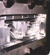
An aluminum test part at NIST's Manufacturing Engineering Laboratory, Gaithersburg, MD, with 0.030" walls and floors is fixtured to the original stock using integral tooling tabs. The tabs are removed with a bandsaw after milling. (Click for larger images)One important field of machining has been noticeably lacking in breakthrough developments-namely workholding. True, over the years equipment manufacturers have steadily improved their design of collets, chucks, and other equipment, but the basic way workpieces are fixtured and otherwise secured for machining has remained unchanged over the years.
That appears to be changing. A wide range of equipment suppliers, end users, university research departments, and government agencies are at work developing radically new workholding techniques. The results of their efforts, both large and small, could dramatically alter how parts are machined in the near future.
One workholding manufacturer, Huron Machine Products Inc., Fort Lauderdale, FL, is developing a system of modular chuck bodies and components that can be arranged to accommodate a broad range of parts. "Template-chuck and top-tooling designs are creating the opportunity to maximize the types of parts that can be formed as well as keeping changeover and cycle times to a minimum," says Richard MacKinnon, director of workholding applications.
"In the past, the focus was to have the part fit the chuck. Now, it's to have the chuck fit the part. It all adds up to an important increase in machine flexibility and utilization."
Another significant development will be announced in a few months by Production Dynamics, Valparaiso, IN. It's a modular lathe chuck with the ability to change quickly from outside diameter to inside diameter (ID) gripping. The device uses a unique system of expanding mandrels and dual-taper sleeves to provide the ID workholding.
The new chuck will also provide fixed-length operation in order to produce consistently accurate part length. It will do this with a fixed-length, pull-back operation that functions accurately with any type of barloader or barfeeder, as well as in manual chucking operations.
Work also is proceeding on the special workholding problems associated with machining very small precision parts. To demonstrate the micromachining capabilities of its FJV-20 vertical machining center, Mazak Corp., Florence, KY, recently machined a tiny brass replica of a giant Caterpillar bulldozer, a 0.33"-long X 0.23"-wide X 0.20"-high model with 17 separate parts. Some of the parts are so delicate that Mazak engineers used an ice-chucker technique to hold them. This involved freezing the individual parts in ice and exposing only the portion to be machined.
The National Institute of Standards and Technology (NIST), Gaithersburg, MD, is currently working on a variety of workholding problems, including those posed by micromachining. One technique it's investigating is machining extremely small parts while they are still attached to the original billet, which in effect functions as the workholder. After machining, the parts are cut off using EDM.
"We're experimenting with very thin-walled parts," says Brad Damazo, a mechanical engineer at NIST's Manufacturing Engineering Laboratory. "We start with an oversized billet of aluminum and machine the walls of the part down to around 0.01" while they're still attached to the original material. We also use an EDM for the cutoff."
A Major Breakthrough?
Of all the work being done in the field of workholding, perhaps nothing is as potentially significant as the intelligent fixturing system (IFS) being developed by Lamb Technicon, Warren, MI, and a consortium of universities, under a research grant awarded earlier this year by NIST.
The IFS is being developed initially for the high-volume production of automotive parts. While not members of the research consortium, Chrysler, Ford, and General Motors are taking an active role in specifying their requirements while continuously evaluating the results of the research. The Big Three automakers see the new system as a way to enhance their ability to reduce the cost of product variation, vary supply to meet demand, and get their new products to market quickly.
"If the project is successful, the resulting technology could eventually save the U.S. auto industry as much as $3 billion to $4 billion annually," claims Philip Szuba, Lamb Technicon's manager of R&D and the lead investigator for the project.
As envisioned by Lamb Technicon and the consortium, which includes Georgia Tech, the University of Michigan, and Penn State University, the IFS will have applications far beyond the auto industry. In addition to the initial grant, Szuba's company will invest several million more dollars to make the IFS a commercial product.
The Big Three will be given first opportunity to use the fixturing system, giving them a huge advantage over foreign vehicle producers. However, after a three- to five-year period, Lamb Technicon will modify the IFS to meet foreign market specifications and will offer the new system worldwide.
Greater Flexibility
According to Szuba, fixed mechanical locators are the critical technology that limits the flexibility of current machining fixtures. The use of IFS will eliminate the need for mechanical locators, thus giving rise to high flexibility and greater machine utilization.
Lamb's IFS project consists of four major subsystems: a flexible clamping system, part-location system, part micropositioner, and a fixture configuration station.
With the IFS, the position of a part is not known with great precision either before or during the clamping cycle. However, after a part is secured, the part-location system is used to precisely locate the part with great speed and accuracy. With the difference between the actual and desired position of the part known, the part micropositioner is used to correct any misalignment and the part is ready to be machined.
The IFS also eliminates the need for the part-qualification process, during which nonfunctional features are machined into the workpiece so that subsequent fixturing can take place. "This change will shift the current paradigm of machining nonfunctional location features," says Szuba, "and remove several machine operations that now take place in such areas as cylinder heads, engine blocks, transmission cases, and exhaust manifolds."
The new fixturing concept also takes advantage of the flexible clamping system that can be reconfigured to hold a family of related parts, thus permitting a high degree of flexibility. All of the elements of the IFS are integrated into the fixture configuration station. It's here that a fixture will be reconfigured automatically to service whichever member of a predetermined family of parts is presented to the machining system.
Part fixturing is a critical and expensive process in the machining of not only automotive parts, but many other kinds of components. In most high-volume machining systems, dedicated fixtures are used to locate and hold parts.
"In recent years, the need to reduce cycle times-partially through more aggressive cutting-has increased the forces that act on the part during machining," Szuba explains. "This drive for productivity has come at the same time that part geometry has often become more complex and with tighter tolerances. This has led to increased problems with fixture-part deformation and vibration."
Current trends in the auto industry are moving toward shorter machining runs on more general-purpose equipment and hence, more frequent changeovers. This trend makes the use of dedicated fixtures increasingly expensive. As a result, there is considerable motivation to develop fixturing concepts and designs that allow for reconfigurability.
Mechanical Locators
A key barrier to the implementation of reconfigurable fixtures is the need for fixed mechanical locators. Locators are used to mate with part features in order to locate the part with respect to the pallet fixture and/or machining station. In addition, the use of mechanical locators requires that both the locators and the mating part features be geometrically precise. This often necessitates the machining of nonfunctional features for subsequent setups. It's especially true for parts that originate as castings or forgings.
Lamb Technicon's vision of the IFS also allows it to be used as an agile fixturing system, consisting of pallet fixtures and a fixture configuration station (FCS). The pallet fixture will be used to transfer parts to and from the machining stations and the FCS via a robot. All part loading/unloading and fixture reconfiguration will occur at the FCS.
Each pallet fixture will have a set of flexible clamps that can be reconfigured to hold any part within a family for any setup. The pallet will also have a micropositioner underneath the flexible clamps that can provide two degrees of controlled, rotational freedom. The micropositioner is used to correct any part misalignment that may occur during the part-loading process.
"In general, fixturing technology has changed little over the past 50 years," Szuba points out. "In order to achieve truly flexible machining systems, a new fixturing paradigm must be developed."
Industry observers believe that machining fixtures of the future will embody most, if not all, of the following performance capabilities:
 The ability to eliminate the use of mechanical locators and nonfunctional machined features as a means of establishing part location.
The ability to be easily reconfigured to accommodate in a single fixture multiple parts within a specific part family.
The ability to be easily reconfigured to accommodate in a single fixture all the setups required to machine all the features on any given part within a specific part family.
An open part-holding system that enables maximum access to multiple part features to reduce the number of reconfigurations required for a given part.
A monitoring system that is able to detect departures from the intended position, with the intelligence to know how to adjust part position in response to such departures.
Sufficient fixture-part rigidity to ensure the viability of aggressive cuts while minimizing vibrations and guaranteeing stable and precise machined-feature generation.
"In addition, software design and analysis tools that enable the scientific evaluation of the performance of a given fixture configuration should be available," says Szuba. "The intent of the IFS project is to realize this new paradigm."
Eliminating Workholding
As long as parts are made on machine tools, there will always be a need for workholding. However, taking their cue from the principles of rapid prototyping, researchers around the country are working on new manufacturing techniques that do not call for traditional workholding devices.
"Early rapid-prototyping systems produced plastic models as their end product," says Dennis Jurrens, an engineer at NIST's Manufacturing Engineering Laboratory who follows developments in the field. "Now the rapid-prototyping industry is moving toward a finished product that can be used without additional machining. Using the layer concept, people are producing finished parts in metal and in composite materials without the need for workholding."
The new techniques are being called by a variety of names, including solid freeform fabrication, layered manufacturing, and desktop manufacturing. "Whatever they're called," says Jurrens, "the goal in each case is the direct production of real parts."
Jurrens believes that widespread use of these new techniques in industry is still a number of years away. "It's getting closer all the time," he points out. "The limiting factors right now are production speed and accuracy, but they're being improved. It will probably be three to five years before it's used to any great extent."
Whatever happens, Jurrens says milling, drilling, turning, and grinding will be with us far into the future. As a result, workholding will continue to be part of the machining process for a long time to come.
About the Author
Robert Eade is a Waterbury, CT-based business writer who has been reporting on trends and issues in metalworking and manufacturing for 35 years.
Related Glossary Terms
- bandsaw
bandsaw
Machine that utilizes an endless band, normally with serrated teeth, for cutoff or contour sawing. See saw, sawing machine.
- chuck
chuck
Workholding device that affixes to a mill, lathe or drill-press spindle. It holds a tool or workpiece by one end, allowing it to be rotated. May also be fitted to the machine table to hold a workpiece. Two or more adjustable jaws actually hold the tool or part. May be actuated manually, pneumatically, hydraulically or electrically. See collet.
- cutoff
cutoff
Step that prepares a slug, blank or other workpiece for machining or other processing by separating it from the original stock. Performed on lathes, chucking machines, automatic screw machines and other turning machines. Also performed on milling machines, machining centers with slitting saws and sawing machines with cold (circular) saws, hacksaws, bandsaws or abrasive cutoff saws. See saw, sawing machine; turning.
- cutting tool materials
cutting tool materials
Cutting tool materials include cemented carbides, ceramics, cermets, polycrystalline diamond, polycrystalline cubic boron nitride, some grades of tool steels and high-speed steels. See HSS, high-speed steels; PCBN, polycrystalline cubic boron nitride; PCD, polycrystalline diamond.
- electrical-discharge machining ( EDM)
electrical-discharge machining ( EDM)
Process that vaporizes conductive materials by controlled application of pulsed electrical current that flows between a workpiece and electrode (tool) in a dielectric fluid. Permits machining shapes to tight accuracies without the internal stresses conventional machining often generates. Useful in diemaking.
- family of parts
family of parts
Parts grouped by shape and size for efficient manufacturing.
- fixture
fixture
Device, often made in-house, that holds a specific workpiece. See jig; modular fixturing.
- gang cutting ( milling)
gang cutting ( milling)
Machining with several cutters mounted on a single arbor, generally for simultaneous cutting.
- grinding
grinding
Machining operation in which material is removed from the workpiece by a powered abrasive wheel, stone, belt, paste, sheet, compound, slurry, etc. Takes various forms: surface grinding (creates flat and/or squared surfaces); cylindrical grinding (for external cylindrical and tapered shapes, fillets, undercuts, etc.); centerless grinding; chamfering; thread and form grinding; tool and cutter grinding; offhand grinding; lapping and polishing (grinding with extremely fine grits to create ultrasmooth surfaces); honing; and disc grinding.
- inner diameter ( ID)
inner diameter ( ID)
Dimension that defines the inside diameter of a cavity or hole. See OD, outer diameter.
- lathe
lathe
Turning machine capable of sawing, milling, grinding, gear-cutting, drilling, reaming, boring, threading, facing, chamfering, grooving, knurling, spinning, parting, necking, taper-cutting, and cam- and eccentric-cutting, as well as step- and straight-turning. Comes in a variety of forms, ranging from manual to semiautomatic to fully automatic, with major types being engine lathes, turning and contouring lathes, turret lathes and numerical-control lathes. The engine lathe consists of a headstock and spindle, tailstock, bed, carriage (complete with apron) and cross slides. Features include gear- (speed) and feed-selector levers, toolpost, compound rest, lead screw and reversing lead screw, threading dial and rapid-traverse lever. Special lathe types include through-the-spindle, camshaft and crankshaft, brake drum and rotor, spinning and gun-barrel machines. Toolroom and bench lathes are used for precision work; the former for tool-and-die work and similar tasks, the latter for small workpieces (instruments, watches), normally without a power feed. Models are typically designated according to their “swing,” or the largest-diameter workpiece that can be rotated; bed length, or the distance between centers; and horsepower generated. See turning machine.
- machining center
machining center
CNC machine tool capable of drilling, reaming, tapping, milling and boring. Normally comes with an automatic toolchanger. See automatic toolchanger.
- metalworking
metalworking
Any manufacturing process in which metal is processed or machined such that the workpiece is given a new shape. Broadly defined, the term includes processes such as design and layout, heat-treating, material handling and inspection.
- milling
milling
Machining operation in which metal or other material is removed by applying power to a rotating cutter. In vertical milling, the cutting tool is mounted vertically on the spindle. In horizontal milling, the cutting tool is mounted horizontally, either directly on the spindle or on an arbor. Horizontal milling is further broken down into conventional milling, where the cutter rotates opposite the direction of feed, or “up” into the workpiece; and climb milling, where the cutter rotates in the direction of feed, or “down” into the workpiece. Milling operations include plane or surface milling, endmilling, facemilling, angle milling, form milling and profiling.
- turning
turning
Workpiece is held in a chuck, mounted on a face plate or secured between centers and rotated while a cutting tool, normally a single-point tool, is fed into it along its periphery or across its end or face. Takes the form of straight turning (cutting along the periphery of the workpiece); taper turning (creating a taper); step turning (turning different-size diameters on the same work); chamfering (beveling an edge or shoulder); facing (cutting on an end); turning threads (usually external but can be internal); roughing (high-volume metal removal); and finishing (final light cuts). Performed on lathes, turning centers, chucking machines, automatic screw machines and similar machines.