Creating close-tolerance holes is common at machine shops. Boring, grinding, broaching and EDMing are a few ways to produce these holes, but reaming can be most efficient depending on the
application.
Multiple Methods
Boring and grinding generate geometrically accurate holes with fine surface finishes. But unlike reaming, boring and grinding require machinists to closely monitor tool condition. Boring tools are adjustable and call for a user to watch hole size and correct for tool wear. They must be reset after an insert is changed or indexed or the cutting edge is sharpened.
Grinding requires a user to periodically dress the grinding wheel, which necessitates adjusting the machine to maintain hole size. Because reamers typically do not allow diametric adjustment, they demand less attention than boring tools and grinding wheels, resulting in a more robust process. Reaming is not only more stable but faster than boring and grinding.
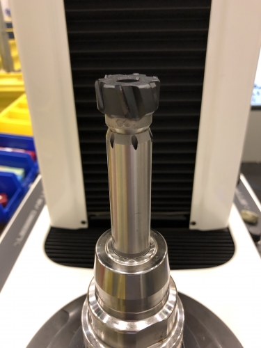
This reamer has a replaceable carbide head, making sharpening easy and allowing users to quickly change sizes with minimal downtime. This style is efficient for repair operations in which volume is low and fast changeover is desired. Image courtesy of C. Tate
Broaching is efficient and accurate. However, broaching tools are expensive, and reconditioning them takes skilled toolmakers and specialized equipment. These costs can be difficult to justify in low-volume, high-mix environments. Reamers are relatively inexpensive and just as accurate with modest reconditioning costs. Machines and personnel for reconditioning reamers are common compared with those for broaching tools, which makes reaming tools more cost-effective.
Reaming and EDMing differ a lot and generally do not have overlapping applications, but the comparison is still worth mentioning. EDMing is excellent for creating tight-tolerance holes, especially in hard materials, yet reaming can be as accurate. Unlike EDMing, which requires a specialized machine tool, reaming may be performed on all traditional machine tools, such as knee mills, lathes and drill presses.
Really Reaming
Reamers are typically made of carbide or HSS and are available in countless diameters and flute styles, so reaming processes have a broad range of applications. In a testament to the efficiency and reliability of reamers, one tool manufacturer offers over 11,000 combinations on its website.
When used correctly, a reamer produces a round, accurately sized hole with a glasslike finish. Reaming operations reasonably should hold diameters to within a ±0.0127 mm (±0.0005") tolerance.
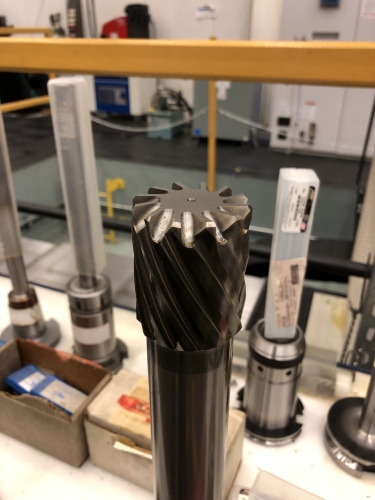
Reamers are available in countless sizes and styles. This reamer has spiral flutes, which enhance chip flow like the spiral flutes on a drill. Image courtesy of C. Tate
Reamers are end-cutting tools. Although their flutes appear capable of side cutting, like endmills, the lip of a flute does not cut. The corner where the flat end and the flutes meet is where work is done. Corners are never square. They usually are chamfered and sometimes have a radius. Corner geometry of the reamer allows it to enter the hole in a way that prevents it from altering the center location of the hole. The noncutting lip of the flute acts as a guide that supports the body of the reamer while in the hole, which stops the tool from wandering off the toolpath. The burnishing action gained from the noncutting lip also enhances surface finishes. When speeds and feeds are optimized, reamers impart a fine finish.
Reaming is a repeatable process and far easier to manage than similar methods, such as boring. Designing a repeatable reaming process is straightforward, but users should consider a few factors.
Key Considerations
Reamers must be sharp. Dull ones result in excessive tool pressure, which causes issues with hole geometry. In relatively soft materials, like aluminum, a dull reamer can deliver oversized holes because of built-up edge. In hard materials, such as tool steels, a dull reamer can lead to galling from poor chip formation.
Hole condition is important. Reamers are finishing tools and do not like taking heavy cuts. Delivering a hole with the optimal amount of stock is critical. Holes need enough stock to allow proper chip formation but not so much stock that a reamer has to exert too much tool pressure. Talking with an application expert at a tool manufacturer may be very helpful.
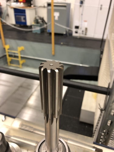
Known as a chucking reamer, this is by far the most common type of reamer. It is inexpensive and effective for the majority of applications. Image courtesy of C. Tate
Before reaming, a hole must be straight. Reamers tend to follow the existing hole, so reaming a crooked hole typically yields another crooked hole. Reaming a crooked hole also can result in an oversize hole diameter.
Minimizing runout is crucial when reaming. Consider a 12.7 mm (0.5") reamer with 0.0127 mm runout. The 0.0127 mm runout would cause the tool to create a 12.7254 mm (0.501") circle when rotated. It can be difficult to maintain a 0.0254 mm (0.001") tolerance when the runout of the tool drives the cutting edge past the upper end of the tolerance before entering the hole.
Some applications absorb small amounts of runout, but it is always best for a tool to run true. Using floating reamer holders that mitigate runout is one way to overcome runout and misalignment. Certain reamers used in high-production, close-tolerance work rely on toolholders that do not float but instead have axial and radial adjustments, which allow removal of almost all runout from a tool. Some of these adjustments are sufficiently critical that they are performed on the machine tool so the reamer is “tuned” to the machine spindle.
I have found that reaming is the most cost-effective, reliable method of finishing close-tolerance holes. Tools are available in countless configurations, making them suitable for low-volume specialty work, like that found in a toolroom, or for high-volume activity, like that found at an engine manufacturing facility.
Related Glossary Terms
- boring
boring
Enlarging a hole that already has been drilled or cored. Generally, it is an operation of truing the previously drilled hole with a single-point, lathe-type tool. Boring is essentially internal turning, in that usually a single-point cutting tool forms the internal shape. Some tools are available with two cutting edges to balance cutting forces.
- broaching
broaching
Operation in which a cutter progressively enlarges a slot or hole or shapes a workpiece exterior. Low teeth start the cut, intermediate teeth remove the majority of the material and high teeth finish the task. Broaching can be a one-step operation, as opposed to milling and slotting, which require repeated passes. Typically, however, broaching also involves multiple passes.
- built-up edge ( BUE)
built-up edge ( BUE)
1. Permanently damaging a metal by heating to cause either incipient melting or intergranular oxidation. 2. In grinding, getting the workpiece hot enough to cause discoloration or to change the microstructure by tempering or hardening.
- burnishing
burnishing
Finishing method by means of compressing or cold-working the workpiece surface with carbide rollers called burnishing rolls or burnishers.
- flat ( screw flat)
flat ( screw flat)
Flat surface machined into the shank of a cutting tool for enhanced holding of the tool.
- flutes
flutes
Grooves and spaces in the body of a tool that permit chip removal from, and cutting-fluid application to, the point of cut.
- galling
galling
Condition whereby excessive friction between high spots results in localized welding with subsequent spalling and further roughening of the rubbing surface(s) of one or both of two mating parts.
- grinding
grinding
Machining operation in which material is removed from the workpiece by a powered abrasive wheel, stone, belt, paste, sheet, compound, slurry, etc. Takes various forms: surface grinding (creates flat and/or squared surfaces); cylindrical grinding (for external cylindrical and tapered shapes, fillets, undercuts, etc.); centerless grinding; chamfering; thread and form grinding; tool and cutter grinding; offhand grinding; lapping and polishing (grinding with extremely fine grits to create ultrasmooth surfaces); honing; and disc grinding.
- grinding wheel
grinding wheel
Wheel formed from abrasive material mixed in a suitable matrix. Takes a variety of shapes but falls into two basic categories: one that cuts on its periphery, as in reciprocating grinding, and one that cuts on its side or face, as in tool and cutter grinding.
- high-speed steels ( HSS)
high-speed steels ( HSS)
Available in two major types: tungsten high-speed steels (designated by letter T having tungsten as the principal alloying element) and molybdenum high-speed steels (designated by letter M having molybdenum as the principal alloying element). The type T high-speed steels containing cobalt have higher wear resistance and greater red (hot) hardness, withstanding cutting temperature up to 1,100º F (590º C). The type T steels are used to fabricate metalcutting tools (milling cutters, drills, reamers and taps), woodworking tools, various types of punches and dies, ball and roller bearings. The type M steels are used for cutting tools and various types of dies.
- reamer
reamer
Rotating cutting tool used to enlarge a drilled hole to size. Normally removes only a small amount of stock. The workpiece supports the multiple-edge cutting tool. Also for contouring an existing hole.
- tolerance
tolerance
Minimum and maximum amount a workpiece dimension is allowed to vary from a set standard and still be acceptable.
- tool steels
tool steels
Group of alloy steels which, after proper heat treatment, provide the combination of properties required for cutting tool and die applications. The American Iron and Steel Institute divides tool steels into six major categories: water hardening, shock resisting, cold work, hot work, special purpose and high speed.
- toolpath( cutter path)
toolpath( cutter path)
2-D or 3-D path generated by program code or a CAM system and followed by tool when machining a part.
Author

Christopher Tate is the owner of Tate Engineering, a Natchez, Mississippi, firm that helps manufacturers solve efficiency problems. Tate, who earned master's degree in industrial technology from Mississippi State University, has 32 years of experience in the metalworking industry.