Finding the grinding sweet spot

Author Jeffrey A. Badger, Ph.D.
Published
August 01, 2014 - 10:30am

Dear Doc: I keep hearing the phrase "grinding sweet spot." What is it and how do I find it?

The Doc Replies: The sweet spot is where the grits in a grinding wheel optimally penetrate the workpiece to form a chip—not too deep and not too shallow. It’s analogous to chip load or chip thickness in milling.

When the grits don’t penetrate deep enough to form a chip (see Region I in the figure), they just rub and generate heat. When grit penetration is too deep (Region III), a chip forms but the grits get ripped from the bond material, causing high wheel wear. When the grits penetrate just deep enough to form a chip (Region II), that’s the sweet spot.

Figure%2c%20aug.tif
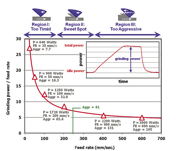
Courtesy of J. Badger

When grinding parts in large batch sizes, operators are pretty good at tweaking speeds and feeds to find the sweet spot. But what if you want to find it quickly? First, get a power meter, ideally one like my Grindometer that outputs true power in watts or horsepower. An alternative is to use the ammeter or load meter on the machine. That’s not as accurate, but will usually get you in the ballpark.

Second, run a few parts at the standard feed rate and measure the power. Remember, you want the grinding power, so you must subtract the power required just to keep the wheel idling. Third, run a few parts at increasingly faster feeds, then at increasingly slower feeds.

Fourth, at each point, note the power in whatever units you want, such as watts, amps or percent of maximum load, and divide it by the feed rate. This is an approximation of the “inefficiency” of the process. Once you have this, plot it against the feed rate. You’ll get a curve like the one in the figure.

Once you’ve found the sweet spot for a combination of wheel, workpiece and machine, you’ll want to keep it by calculating the aggressiveness number:

Equation%20in%20PP.tif

Let’s say we find our sweet spot at a feed rate, or workpiece speed, of 15,000 mm/min. Plugging in the other values (DOC is 0.020mm, wheel diameter is 250mm and wheel speed is 27.5 m/sec.) gives an aggressiveness number of 81. This number is used for roughing, when the wheel is doing most of the work. Choose any DOC, feed rate or wheel speed you want, as long as the combination produces an aggressiveness number of 81. When finishing, a smaller value is OK and will help impart a fine surface finish.

My customers have been using this concept for years and enjoying huge benefits. They find that, when roughing, they are always at or near the wheel’s sweet spot. They have fewer burn problems (frequently caused by an aggressiveness number that’s too low), less wheel wear (frequently caused by an aggressiveness number that’s too high) and generally get better results. CTE

About the Author: Dr. Jeffrey Badger is an independent grinding consultant, visiting companies and helping them improve their grinding operations. His Web site is www.TheGrindingDoc.com. He’ll be giving his High Intensity Grinding Course in Las Vegas Oct. 20-22 and in Chicago Dec. 3-5, hosted by Greenlee Diamond Tool.

Related Glossary Terms

  • feed

    feed

    Rate of change of position of the tool as a whole, relative to the workpiece while cutting.

  • gang cutting ( milling)

    gang cutting ( milling)

    Machining with several cutters mounted on a single arbor, generally for simultaneous cutting.

  • grinding

    grinding

    Machining operation in which material is removed from the workpiece by a powered abrasive wheel, stone, belt, paste, sheet, compound, slurry, etc. Takes various forms: surface grinding (creates flat and/or squared surfaces); cylindrical grinding (for external cylindrical and tapered shapes, fillets, undercuts, etc.); centerless grinding; chamfering; thread and form grinding; tool and cutter grinding; offhand grinding; lapping and polishing (grinding with extremely fine grits to create ultrasmooth surfaces); honing; and disc grinding.

  • grinding wheel

    grinding wheel

    Wheel formed from abrasive material mixed in a suitable matrix. Takes a variety of shapes but falls into two basic categories: one that cuts on its periphery, as in reciprocating grinding, and one that cuts on its side or face, as in tool and cutter grinding.

  • milling

    milling

    Machining operation in which metal or other material is removed by applying power to a rotating cutter. In vertical milling, the cutting tool is mounted vertically on the spindle. In horizontal milling, the cutting tool is mounted horizontally, either directly on the spindle or on an arbor. Horizontal milling is further broken down into conventional milling, where the cutter rotates opposite the direction of feed, or “up” into the workpiece; and climb milling, where the cutter rotates in the direction of feed, or “down” into the workpiece. Milling operations include plane or surface milling, endmilling, facemilling, angle milling, form milling and profiling.

  • web

    web

    On a rotating tool, the portion of the tool body that joins the lands. Web is thicker at the shank end, relative to the point end, providing maximum torsional strength.