Computer-aided error detection and prevention routines for CAM programs not only help prevent disaster—they improve machine efficiency too.
CAM programs enable CNC machine tools to make parts with speeds, accuracies and repeatabilities unimagined by the manual machinists of old. However, as with any digital technology, the rule of garbage-in, garbage-out holds firm.
A CAM program can run an erroneous toolpath just as fast and faithfully as it does a perfect one. The increasing complexity of machined parts, the growing capabilities of machine tools and a scarcity of experienced programmers magnify the need for error recognition and prevention at the part-programming stage of machining operations. Cutting Tool Engineering talked to suppliers and users of CAM software, machining simulation programs and machine tools to explore the sources of programming errors and the efforts to detect them before the mistakes produce wasted time, scrap and even machine tool damage.
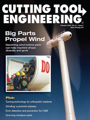
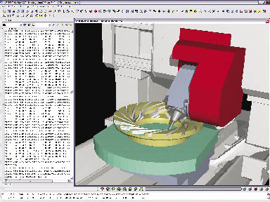
Courtesy of Haas Automation
Milton Ramirez, product technical specialist for Haas Automation, sets tool offsets using the Haas Intuitive Programming System. The operator selects workpiece material, tool type and tool material during setup, and the IPS uses that information to calculate safe speeds and feeds for the part program.
Sources of Error
Familiarity breeds competence, but inexperience breeds mistakes. A new programmer is more likely to make programming errors than an experienced one. Vytas Cijunelis, Midwest operations manager for DP Technology Corp., Camarillo, Calif., developer of Esprit software, said, “It is luck or an extreme gift if someone can ‘hit the street running’ from the get-go. Mozart wrote some great music when he was 5, but that’s pretty rare. Most of us have to work at [programming]. Most of us have to do it over and over to make the process more secure.”
In addition to the retirement of veteran programmers and the declining popularity of machining careers in general, changes in manufacturing technology are giving rise to a new group of programmers unfamiliar with machining practices. Steve Bertrand, sales manager for CNC Software Inc., Tolland, Conn., supplier of Mastercam software, calls this growing group “nontraditional” CAM programmers. An example is producers of rapid prototypes who need to reproduce polymer models made on rapid-prototyping machines as prototypes or parts machined from steel or aluminum. “These guys are buying tabletop machines, and they are making some of the prototypes in their offices, machining them for the first time. They are just learning,” Bertrand said.
Bill Hasenjaeger, product marketing manager for CGTech, Irvine Calif., which provides Vericut verification and simulation software, said common programming errors caused by lack of experience include setting an overly aggressive material-removal rate, programming inefficient motion during machining and missing features entirely.
Even veteran programmers, however, can be rushed into making programming mistakes when dealing with the fast turnover and small lot sizes required for just-in-time production demands. Hasenjaeger said these errors include programming toolpaths that gouge or undercut the design geometry or roughing routines that leave too much or too little material for subsequent operations. Tooling-related mistakes include toolpaths that result in the shank of the tool assembly rubbing on the part’s sidewall or improper ramping or plunge-cutting with a noncenter-cutting endmill. Spindle mistakes can involve setting the spindle to turn in the wrong direction or at speeds or feed rates that are too high or too low.
Hasenjaeger added that increasingly complex parts and machine tools create their own set of unexpected mistakes and problems; 5-axis material removal can result in unintended cutter contact with fixturing or machine components, and multifunction mill/turn tooling configurations may produce unanticipated collisions as well. At best, programming errors will result in lower part quality and lower production rates; at worst, broken tools and even machine tool damage can occur.
Error Detection and Prevention
As a result, CAM suppliers provide tools to help avoid programming errors. DP Technology’s Cijunelis said Esprit software, for example, contains a database of tools, speeds and feeds for common workpiece materials. “It will look for each of the tools that you are using and go to the appropriate settings and put those into the operation pages. It is a one-step process.” Cijunelis added that the parameters may not exactly match a particular shop’s practices. “You talk to 10 guys who want to cut aluminum, they are all going to tell you a different speed and feed to use because of cutter or machining strategy,” he said. Nonetheless, the database’s recommendations are intended to eliminate errors across a range of machines and operations.
User-determined rules are another error-prevention feature. “For example, you can set rules so you can’t cut deeper than 10 percent of the tool diameter, or you can’t make a step-over greater than 50 percent of the tool diameter,” Cijunelis said. “There are a lot of things that you can do that will prevent you from [programming] something in that you shouldn’t. It depends, of course, on if and how the user wants to use these features. The user can set up to machine parts the way he wishes and automatically call up the proven processes again and again.”
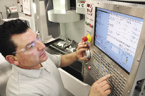
Courtesy of CNC Software
One error-prevention strategy for CAM programs involves adding a degree of automation to the programming process. For example, Mastercam says its Feature Based Machining automatically creates toolpaths to machine features that are detected and identified via user criteria.
Another error-prevention strategy involves adding a degree of automation to the programming process. According to CNC Software’s Bertrand, Mastercam’s Feature Based Machining (FBM) eliminates manual feature identification for programming milling and drilling operations on prismatic (geometrically shaped) parts. Toolpaths are created automatically to machine features, and FBM output can be refined to meet user-selected criteria such as choosing tools only from a certain specified group of tools or tapping a hole in a specified way.
Bertrand said the automation helps inexperienced programmers by making the decisions required to machine a part in a logical sequence of events, using best practices. An experienced CAM programmer, on the other hand, may use FBM-generated programs as a starting point to generate basic toolpaths. “You have the ability to go back and tailor it and tweak it so it’s exactly the way you want it to be,” Bertrand said. Mastercam’s milling FBM handles “pocketing, contouring, drilling, tapping, boring, countersinking and things of that nature on what we call a production-type part, or prismatic part,” Bertrand said.
Simulation
DP Technology’s Cijunelis said simulation is a key step in error-free programming. “A lot of people use simulation throughout the program. You program a few operations, then you simulate; then you program a few more, then you simulate. You know exactly where the error occurs because the simulation stops and tells you. Having this information, you know exactly what to change to optimize your NC program prior to sending it to the machine. In Esprit, you always have the NC block-by-block information of the tool associated with the operation being simulated.”
CGTech’s Hasenjaeger pointed out that before a part is machined, a CAM program must be translated through post-processing software to create the G code that actually dictates machine movements. He said a CAM system checking its own NC path is “like a student grading his own test. It is not a comprehensive check and common errors can still reach the shop floor and waste valuable machine time and shop resources.”
Hasenjaeger said CGTech’s Vericut verification and simulation software checks the machining program after post-processing and detects feed errors, potential crashes/collisions, gouges, overcutting or undercutting, syntax errors in G code and other procedural details. The software then generates a report that identifies the errors and highlights the relevant lines from the NC program so the problem can be corrected.
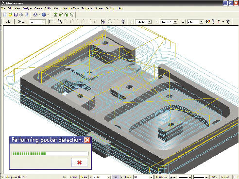
Courtesy of DP Technology
This simulation in Esprit CAM software from DP Technology depicts synchronization of three tool turrets on a mill/turn machine. Synchronizing turrets prevents collisions and enables programmers to maximize utilization of each turret in relation to the others.
Toolpath verification after post-processing is important at Moscow Mills Manufacturing Services, Stowe, Vt., which serves customers in the aerospace, robotics, semiconductor, R&D and general industrial markets. Owner Anderson Leveille described the shop’s niche as prototype to short-run production of high-end, extremely tight-tolerance parts made of materials such as titanium and Inconel. He said simulation and verification after post-processing is particularly relevant in his operation because the shop modifies its post-processors on an ongoing basis. “We are continually working on our posts because at the end of the day, we are always looking for better ways to do things,” he said. A change in a post-processor might involve adding the capability to precall a tool from a mill’s toolchanger while another tool is in the cut. “In other words, you don’t have to wait for your carousel to rotate; a tool will be waiting when the tool arm comes around,” Leveille said. “A post is never perfect, so running the simulation after the post will take care of all these tweaks.”
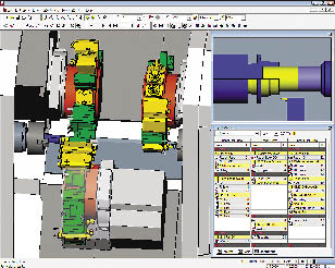
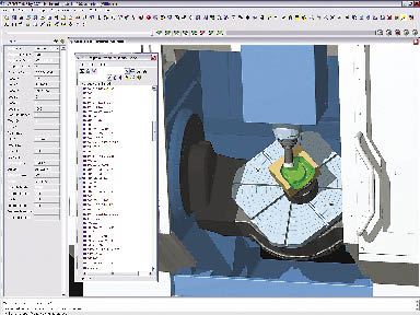
Courtesy of CGTech
This simulation in Vericut software shows the gimbal holding a 5-axis milling head colliding with the part being machined. Vericut verification and simulation software checks the machining program after post-processing and detects feed errors, potential crashes/collisions, gouges, over/undercutting, syntax errors in G codes and other procedural details.
In one example, Leveille said, the CAM simulation of toolpaths involved in machining a complex plastic component “looked beautiful.” However, when an operator posted a new version of the program on the machine, “the thing just did a crazy move and drove the cutter straight across the part. Thankfully, it didn’t smash our machine up. It would be an issue to have a $350,000 to $400,000 5-axis machine and drive a $30,000 spindle into a $100,000 rotary table.”
Moscow Mills recently installed Vericut software. “Vericut is a second filter to make sure that your toolpaths are actually not going to have an issue such as that,” Leveille said.
In addition to avoiding crashes, reliable simulation is important when machining low-volume, high-value parts, he said: “One of the most expensive things that you do is proof a part. When making a quantity of one ultracomplex titanium component with tolerances in the 0.0002 " range true position to a, b and c on certain features, do you proof?” Reliable simulation, he said, can help minimize the expensive process of dry runs and proofing of these parts.
Leveille added that a common stumbling block in the programming process often originates outside his shop, when a customer’s solid model doesn’t match the print. “We are constantly looking out for that sort of thing,” he said. “Some companies say use the solid as the master, and some say use the print as a master. So we are constantly comparing solids to prints and digging out issues.” Leveille said the model-to-part process is rarely as simple as running the model through the CAM system, loading the program into the machine control and pressing the start button. “You have to have your sixth sense on at all times.” He cited an example where a bore on a part might be called out +0.0005 "/ -0.0000 ", “and we are making the mating part, and the tolerance doesn’t look like those two parts are going to fit together.” When it comes to resolving model/print conflicts, Leveille said, “our goal is to ensure that our customers get what they need, not necessarily what they ordered.”
Programming at the Machine
Error-prevention tools are also available to shops that program parts at the machine. According to Milton Ramirez, product technical specialist at machine tool builder Haas Automation Inc., Oxnard, Calif., the company’s conversational Intuitive Programming System (IPS) can detect a variety of programming errors.
In programming a part with IPS, the operator is instructed to enter information regarding the desired operation, workpiece material, part dimensions and tools that will be applied. The system provides default speed and feed values. Users can alter the values if desired, but the system issues warning messages for values that exceed machine capacity. “For every box that you fill in on the IPS pages, there are instructions or messages on the bottom right side. They will tell you if there is any problem and what the problem is,” Ramirez said.
Courtesy of CGTech
This Vericut simulation includes a window listing the G code used to run the machine. An arrow indicates the line of code directing the machine’s current action.
When the part program is complete, it is presented in a graphic representation on the control screen. “Visually,” Ramirez said, “it is a 2-D presentation, not a 3-D, isometric graphic like you would see on a computer system, but it does what you need. It is very useful because it will check your program, make sure there are no errors and you can also see what it is going to do when you run it.” Ramirez pointed out that the verification process is performed on the G code that actually runs the machine tool.
Also, not every programming problem is an error. CGTech’s Hasenjaeger said: “Inefficient processes are sometimes more costly than outright mistakes because the inefficiency usually continues for months or years and no one notices. The attitude is often, ‘Hey, the process is working, parts are being made, why worry?’ But not considering inefficient processes as errors is a big mistake, especially when competing in a global marketplace. Using process optimization products can cut machining time dramatically and reduce many incidental costs by improving tool life, reducing operator fatigue, reducing electrical usage and reducing machine wear.”
Error Through Ignorance
Perhaps the more significant errors associated with CAM programming might be described as programming that never occurs. According to DP Technology’s Cijunelis, shops often err when “they stick to what they know and don’t take into account new software features to help them program more effectively and more quickly.” He said many mistakes are made by programmers who decide to do something by hand that actually can be handled by the computer in an error-free way. He cited an example of programming a wrapped milling operation on a rotary part. Such a program would take hours to write by hand and provide multiple opportunities to make mistakes. “You are typing a bunch of numbers into a computer and you forget one, or you miss a decimal point. There are just so many things that can go wrong when you start doing drone-type work,” Cijunelis said. “The nice thing about CAM is that a lot of these routines are automated now. In a few mouse clicks, the CAM software will output optimized NC code. It eliminates a lot of errors and at the same time is easier and more secure.”
Ben Mund, CNC Software’s marketing manager, said in addition to seeking the latest CAM technology, shops should explore and exploit what they already have. He named the feed rate optimization utility in Mastercam as an example. The utility analyzes the volume of material being removed and the capabilities of the machine tool in use and then generates feeds tailored to maximize efficiency for the specific operation. “It will change the feed rate of every line of code to optimize it for your machine,” he said. “It has been in the software for years, and we find that many users are not even aware that it is there. That’s one of those things that doesn’t cost them any extra money because they already have it.”
Admittedly, it’s not easy for shops to find the time to thoroughly review the capabilities of their software. CNC Software’s Bertrand said programmers get used to using software one way as they try to get the jobs out the door. “Unfortunately, in the real world of manufacturing, there isn’t always enough time to learn.”
There are resources that can help shops get maximum value out of their CAM software without investing too much time. “If there is an active user forum for customers, that is a great place to just hop on and get tips,” Mund said. “People point out great tools that you may not know about because you haven’t had the opportunity to run into them.” Forum participants often are highly knowledgeable, he said, especially regarding details of specific applications. Staying in touch with the software reseller, who can point out improvements and features, is another worthwhile strategy, as is taking advantage of the information posted on software provider’s Web site.
Responsibility Required
Despite the many types and levels of error detection and prevention features available in CAM systems, a degree of responsibility and common sense is still required on the part of the user. “There’s nothing that is so automatic that it is foolproof,” Bertrand said. “Some people do expect that, but it’s not realistic.”
Regarding egregious errors, such as programming a tool to run in an Inconel part at parameters appropriate for machining aluminum, DP Technology’s Cijunelis said “we don’t see that very often, if ever. Something like that you’re almost doing on purpose.”
In addition to demanding some responsibility on the part of the programmer, truly productive CAM programming also requires a level of skill. “A lot of people make the claim that the hands-on art of machining parts has been lost because of computers and the rest of it,” Moscow Mills’ Leveille said. “Well, I would counter that all of that art exists, it’s simply more so. Now the guys on the shop floor, the good ones, are using different pieces of technology to apply the same skills and perceptiveness. They can spend more of their time on the finer details because they are not tied up in the minutia of doing some insane trigonometry calculation to figure out how to get a feature cut on a manual machine.”
“Complexity of machine or cutting process simply adds to the issue,” Cijunelis said, “but with the best software tools at one’s side, we can do a good job and minimize errors as much as possible.” CTE
About the Author: Bill Kennedy, based in Latrobe, Pa., is contributing editor for Cutting Tool Engineering. He has an extensive background as a technical writer. Contact him at (724) 537-6182 or by e-mail at [email protected].
Contributors
CGTech
(949) 753-1050
www.cgtech.com
CNC Software Inc.
(800) 228-2877
www.mastercam.com
DP Technology Corp.
(800) 627-8479
www.dptechnology.com
Haas Automation Inc.
(800) 331-6746
www.haascnc.com
Moscow Mills Manufacturing Services
(802) 253-2036
www.moscow-mills.com
Related Glossary Terms
- 2-D
2-D
Way of displaying real-world objects on a flat surface, showing only height and width. This system uses only the X and Y axes.
- 3-D
3-D
Way of displaying real-world objects in a natural way by showing depth, height and width. This system uses the X, Y and Z axes.
- boring
boring
Enlarging a hole that already has been drilled or cored. Generally, it is an operation of truing the previously drilled hole with a single-point, lathe-type tool. Boring is essentially internal turning, in that usually a single-point cutting tool forms the internal shape. Some tools are available with two cutting edges to balance cutting forces.
- computer numerical control ( CNC)
computer numerical control ( CNC)
Microprocessor-based controller dedicated to a machine tool that permits the creation or modification of parts. Programmed numerical control activates the machine’s servos and spindle drives and controls the various machining operations. See DNC, direct numerical control; NC, numerical control.
- computer-aided manufacturing ( CAM)
computer-aided manufacturing ( CAM)
Use of computers to control machining and manufacturing processes.
- countersinking
countersinking
Cutting a beveled edge at the entrance of a hole so a screw head sits flush with the workpiece surface.
- endmill
endmill
Milling cutter held by its shank that cuts on its periphery and, if so configured, on its free end. Takes a variety of shapes (single- and double-end, roughing, ballnose and cup-end) and sizes (stub, medium, long and extra-long). Also comes with differing numbers of flutes.
- fatigue
fatigue
Phenomenon leading to fracture under repeated or fluctuating stresses having a maximum value less than the tensile strength of the material. Fatigue fractures are progressive, beginning as minute cracks that grow under the action of the fluctuating stress.
- feed
feed
Rate of change of position of the tool as a whole, relative to the workpiece while cutting.
- gang cutting ( milling)
gang cutting ( milling)
Machining with several cutters mounted on a single arbor, generally for simultaneous cutting.
- just-in-time ( JIT)
just-in-time ( JIT)
Philosophy based on identifying, then removing, impediments to productivity. Applies to machining processes, inventory control, rejects, changeover time and other elements affecting production.
- milling
milling
Machining operation in which metal or other material is removed by applying power to a rotating cutter. In vertical milling, the cutting tool is mounted vertically on the spindle. In horizontal milling, the cutting tool is mounted horizontally, either directly on the spindle or on an arbor. Horizontal milling is further broken down into conventional milling, where the cutter rotates opposite the direction of feed, or “up” into the workpiece; and climb milling, where the cutter rotates in the direction of feed, or “down” into the workpiece. Milling operations include plane or surface milling, endmilling, facemilling, angle milling, form milling and profiling.
- numerical control ( NC)
numerical control ( NC)
Any controlled equipment that allows an operator to program its movement by entering a series of coded numbers and symbols. See CNC, computer numerical control; DNC, direct numerical control.
- robotics
robotics
Discipline involving self-actuating and self-operating devices. Robots frequently imitate human capabilities, including the ability to manipulate physical objects while evaluating and reacting appropriately to various stimuli. See industrial robot; robot.
- shank
shank
Main body of a tool; the portion of a drill or similar end-held tool that fits into a collet, chuck or similar mounting device.
- solid model
solid model
3-D model created using “building blocks.” This is the most accurate way of representing real-world objects in CAD.
- step-over
step-over
Distance between the passes of the toolpath; the path spacing. The distance the tool will move horizontally when making the next pass. Too great of a step-over will cause difficulty machining because there will be too much pressure on the tool as it is trying to cut with too much of its surface area.
- tapping
tapping
Machining operation in which a tap, with teeth on its periphery, cuts internal threads in a predrilled hole having a smaller diameter than the tap diameter. Threads are formed by a combined rotary and axial-relative motion between tap and workpiece. See tap.
- tolerance
tolerance
Minimum and maximum amount a workpiece dimension is allowed to vary from a set standard and still be acceptable.
- toolchanger
toolchanger
Carriage or drum attached to a machining center that holds tools until needed; when a tool is needed, the toolchanger inserts the tool into the machine spindle. See automatic toolchanger.
- toolpath( cutter path)
toolpath( cutter path)
2-D or 3-D path generated by program code or a CAM system and followed by tool when machining a part.
- undercut
undercut
In numerical-control applications, a cut shorter than the programmed cut resulting after a command change in direction. Also a condition in generated gear teeth when any part of the fillet curve lies inside of a line drawn tangent to the working profile at its point of juncture with the fillet. Undercut may be deliberately introduced to facilitate finishing operations, as in preshaving.
- web
web
On a rotating tool, the portion of the tool body that joins the lands. Web is thicker at the shank end, relative to the point end, providing maximum torsional strength.