The difficulties of tapping: Drilling Performance
My machining career started at our family machine shop. When I began, we had only conventional, or manual, machine tools. Bridgeports from the 1960s, a Monarch 10EE toolroom lathe built in 1946 and a Lodge & Shipley lathe with a placard announcing that it conformed to the specifications of the War Production Board from World War II were some of the machines I used while learning the craft.
My machining career started at our family machine shop. When I began, we had only conventional, or manual, machine tools. Bridgeports from the 1960s, a Monarch 10EE toolroom lathe built in 1946 and a Lodge & Shipley lathe with a placard announcing that it conformed to the specifications of the War Production Board from World War II were some of the machines I used while learning the craft.
I learned how to tap holes by hand with a tap wrench and tap block. Sometimes, I would “power tap” with the Bridgeport or use the tailstock of a lathe. Other times, I employed methods that even the saltiest of machinists might question, like using a ½”-dia. drill motor to make threads in large castings.
Rarely having any trouble, it is fair to say I was adept at tapping holes. However, when our first CNC machine tool arrived in 1995, tapping became the bane of my existence. Broken taps, bad surface finishes, oversized holes and scrapped parts quickly were the norm. It was as if I had forgotten how to tap holes.
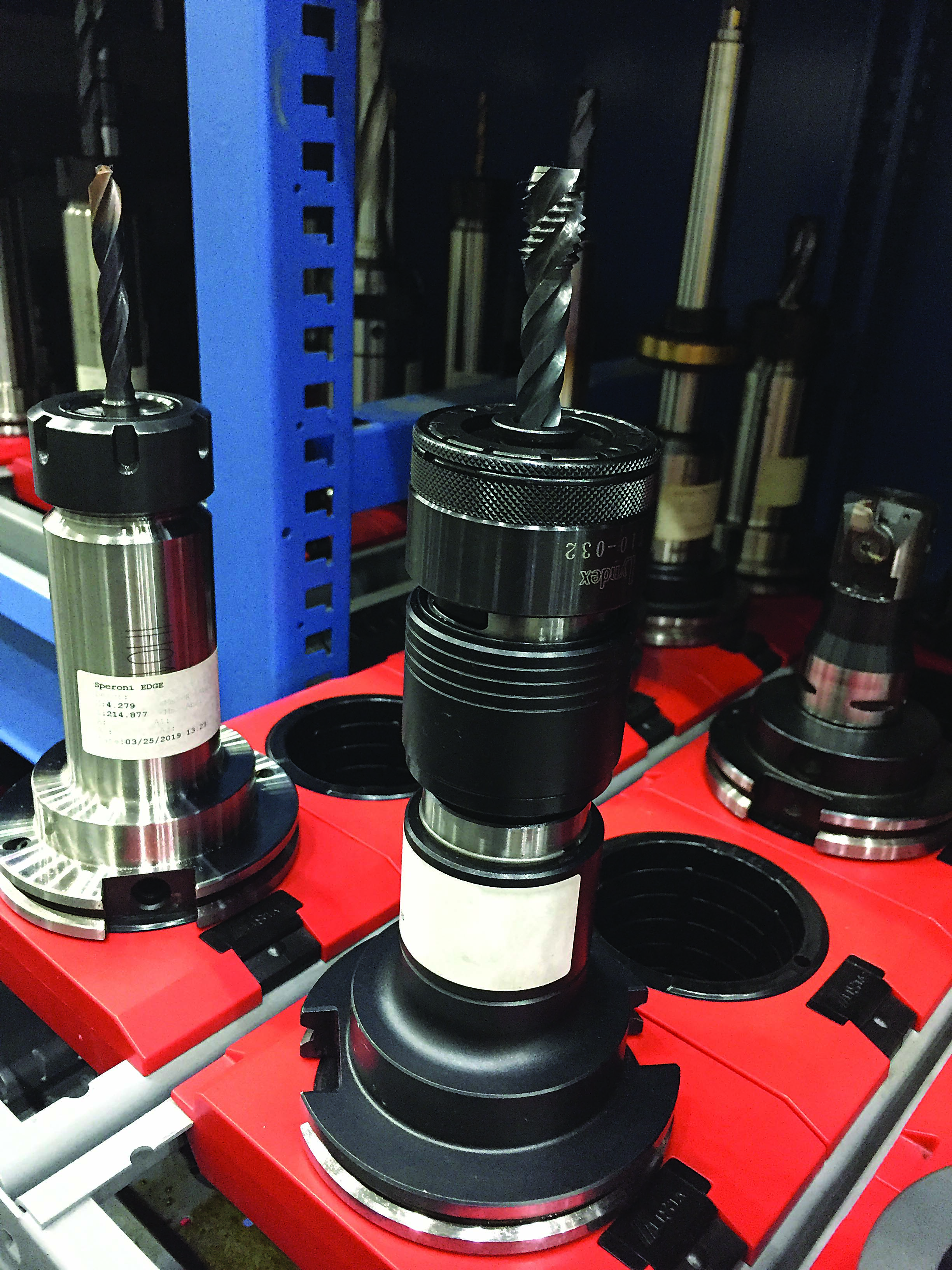
Mitsubishi Hitachi Power Systems Americas has the rigid tapping option on its controls but uses tension compression holders like this one to give another level of protection from errors in programming or setup. Image courtesy of C. Tate
After research and consultation with experts, along with practice on the machine, I realized I had to change my approach. Tapping methods used on conventional machines were not going to work on the machining center.
Sensory Focus
When tapping on a conventional machine, a machinist constantly adjusts to sights and sounds, and this ability to closely interact with the tapping operation allows a lot of leeway in tap selection. With conventional machines, it was common for us to apply inexpensive hand taps for everything, including power tapping. Tapping on a machining center prevents a machinist from being actively engaged in the process and removes the ability to use his senses for guidance while the tap is in the hole.
With a machining center, a machinist can’t stop in the middle of a tapping operation when something sounds or feels wrong. You know that something is incorrect only after a tap is broken or threads are bad. Having the correct tap geometry is critical when tapping on a machining center. There is no time to react to a poor situation caused by using the wrong tool. I learned fast that taps have features designed for specific applications. Using a tap in an application for which it was not designed yielded lousy results and frustration.
Holding and driving taps on conventional machines was done using collets, drill chucks, tap wrenches (held by hand) and, in the crudest setups, adjustable wrenches.
Review the print ads from this magazine to continue
This quick advertiser review unlocks the rest of the article and keeps the full-screen reader focused on the ads instead of the page chrome.


MFGAxis Discussion