When I was working in a machine shop in 1981, Vern moved me from hand screws to NC lathes. My first task there was turning Inconel stator rings. “This’ll give you something to cut your teeth on,” he said, laughing.
Thin like a slice off a soup can, the rings required a 0.001" tolerance on the bore and concentricity of half that for the chucking diameter. After 2 days and a box of scrap parts, I convinced Vern that collets and 3-jaw chucks weren’t going to cut the mustard and got him to spend $5,000 on an air chuck and a set of pie jaws. Boy, did he gripe about the price.
With the air chuck, the tolerances became manageable, but barely—triangulation remained a problem no matter how accurately I bored the jaws and the chuck would start to open around 2,000 rpm, so I never could achieve the spindle speeds I wanted. The good news is Vern gave me a nice raise.
In hindsight, a diaphragm chuck would have been a better solution. Lee Flick, vice president of workholding supplier Pioneer N.A., Elk Grove Village, Ill., said diaphragm chucks are ideal for parts like these. “The advantage is very accurate control of clamping pressure. You can grab thin-walled parts or delicate materials, such as glass or plastic, without damaging the workpiece,” he said.
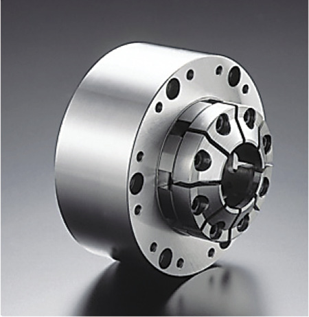
A diaphragm chuck from Pioneer N.A.
Flick explained that diaphragm chucks use an expanding gland. This means there are no sliding parts as in a conventional chuck. Imagine bolting a set of jaws to the face of a steel pie tin. When you push on the opposite side of the tin, right at the center, the jaws open. Load a part, release the pressure and the metal returns to its original shape, thus securing the workpiece (see diagram below).
Granted, the actual mechanism is more complex than our pie tin example, but the lesson is that diaphragm chucks are repeatable and accurate—runout of 0.00002 " is typical. And because the business end of a diaphragm chuck is smooth, there are no nooks and crannies where bits of metal or grinding grit can hide, making them ideal for abrasive environments, such as grinding and hard turning.
They’re also capable of holding at high speeds. Where my 1981-vintage air chuck gave up the ghost at 2,000 rpm, diaphragm chucks today can easily achieve three times that speed with no loss in clamping force. Paul DeFeo, vice president and COO of workholding provider Northfield Precision Instrument Corp., Island Park, N.Y., said this is possible because diaphragm chucks are easy to counterbalance. “We’ll often place a counterweight on the backside of the diaphragm to counteract the hysteresis effect induced by the jaws. In some cases, we can go up to 15,000 rpm without losing pressure.”
However, a diaphragm chuck is roughly twice the price of that air chuck Vern was so reluctant to buy. They’re not effective at holding shafts and other long, skinny parts either, at least not without tailstock support or chuck modifications. In these cases, Pioneer offers a double-diaphragm chuck that contains two plates and corresponding jaw sets: one to grip the front of a long workpiece and the other to hold the back.
Diaphragm chucks can also be a challenge to set up. All of the suppliers interviewed for this article agreed that the lion’s share of top jaws used on diaphragm chucks are machined and ground by the chuck manufacturer. That’s not to say shops can’t make their own jaws; the process is similar to machining jaws for conventional chucks. But diaphragm chucks are ultraprecision workholding devices and making effective ones requires an expert touch.
Depending on the configuration, that service costs $1,500 to $15,000 and up. This is one reason the majority of diaphragm chucks are sold to high-volume parts manufacturers, where accuracy and uptime are critical. “Automotive suppliers are probably the biggest users,” DeFeo said. “Valve seats, fuel injection components, the list goes on.”
Because they are sealed, diaphragm chuck maintenance is virtually nonexistent, and claims of 10 to 15 years of uninterrupted service are typical. Another advantage is the elimination of part lift. “With a 3-jaw chuck, there’s always a lifting effect when the workpiece is clamped,” said Nicholas Fink, president of MicroCentric Corp., a workholding supplier based in Plainview, N.Y. “With a diaphragm chuck, the workpiece is actually pulled down against the locating surface. This provides better repeatability and squareness than that provided by air or hydraulic chucks, and also reduces the chance of part movement during machining.”
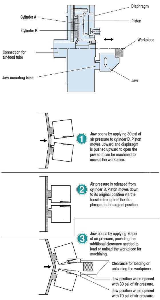
How a typical diaphragm chuck works (side view in all diagrams). Graphics courtesy of Pioneer N.A.
Fink said this cheek-to-cheek waltz between chuck and workpiece offers another benefit. In automated applications where air-gap sensing verifies part placement, diaphragm chucks have a clear advantage—all that’s required is a small compressed air hole in the bottom of the jaw. Upon closing, the workpiece is pulled down, stopping the airflow and signaling to the machine that the part is properly clamped.
Diaphragm chucks aren’t limited to ultraprecision finishing operations. “We’ve had customers use them for castings, for example, where accuracy isn’t necessarily the driving factor in workholding selection,” Fink said. “In this case, it’s easy to create multiple jaw configurations—5-jaw and 8-jaw designs are easy to build. That’s not the case with conventional power chucks.”
Diaphragm chucks come in various sizes. Chris Brown, general manager for North American workholding at Forkardt USA, Traverse City, Mich., said the company offers chucks up to 50 " in diameter. “We have an agricultural customer using 26 " diaphragms to machine large, thin-walled gear rings. We clamped directly on the pitch diameter, greatly improving the part runout. As a result, the customer could leave less stock for finish grinding after heat treatment.”
Nor are diaphragm chucks limited to a delicate touch. Brown said a drawbar is often used to supply additional clamping pressure. “Typically, you’re using only the force of the spring steel to grip the part. That would be applicable for a finishing operation. In some instances, however, we’ll utilize a threaded stud on the back side of the diaphragm and attach a drawbar to it, then use a cylinder at the end of the machine to pull the diaphragm shut.”
Diaphragm chucks are a maintenance-free solution for high-volume production, as well as when making delicate or tight-tolerance parts that can’t be gripped with conventional chucks. While costly and often requiring custom top jaws, diaphragm chucks can be the perfect workholder for challenging parts. CTE
About the Author: Kip Hanson is a contributing editor for CTE. Contact him at (520) 548-7328, or by e-mail at [email protected].Related Glossary Terms
- abrasive
abrasive
Substance used for grinding, honing, lapping, superfinishing and polishing. Examples include garnet, emery, corundum, silicon carbide, cubic boron nitride and diamond in various grit sizes.
- chuck
chuck
Workholding device that affixes to a mill, lathe or drill-press spindle. It holds a tool or workpiece by one end, allowing it to be rotated. May also be fitted to the machine table to hold a workpiece. Two or more adjustable jaws actually hold the tool or part. May be actuated manually, pneumatically, hydraulically or electrically. See collet.
- grinding
grinding
Machining operation in which material is removed from the workpiece by a powered abrasive wheel, stone, belt, paste, sheet, compound, slurry, etc. Takes various forms: surface grinding (creates flat and/or squared surfaces); cylindrical grinding (for external cylindrical and tapered shapes, fillets, undercuts, etc.); centerless grinding; chamfering; thread and form grinding; tool and cutter grinding; offhand grinding; lapping and polishing (grinding with extremely fine grits to create ultrasmooth surfaces); honing; and disc grinding.
- hard turning
hard turning
Single-point cutting of a workpiece that has a hardness value higher than 45 HRC.
- numerical control ( NC)
numerical control ( NC)
Any controlled equipment that allows an operator to program its movement by entering a series of coded numbers and symbols. See CNC, computer numerical control; DNC, direct numerical control.
- pitch
pitch
1. On a saw blade, the number of teeth per inch. 2. In threading, the number of threads per inch.
- titanium nitride ( TiN)
titanium nitride ( TiN)
Added to titanium-carbide tooling to permit machining of hard metals at high speeds. Also used as a tool coating. See coated tools.
- tolerance
tolerance
Minimum and maximum amount a workpiece dimension is allowed to vary from a set standard and still be acceptable.
- turning
turning
Workpiece is held in a chuck, mounted on a face plate or secured between centers and rotated while a cutting tool, normally a single-point tool, is fed into it along its periphery or across its end or face. Takes the form of straight turning (cutting along the periphery of the workpiece); taper turning (creating a taper); step turning (turning different-size diameters on the same work); chamfering (beveling an edge or shoulder); facing (cutting on an end); turning threads (usually external but can be internal); roughing (high-volume metal removal); and finishing (final light cuts). Performed on lathes, turning centers, chucking machines, automatic screw machines and similar machines.
Author

Kip Hanson is a contributing editor for Cutting Tool Engineering magazine. Contact him by phone at (520) 548-7328 or via e-mail at [email protected].