The research projects don’t take place at just one site. Instead, researchers from the participating universities and companies work at their own facilities and share information with each other. The researchers include students, faculty, engineers and R&D teams.
MTAMRI’s purpose is to advance technologies related to the design, manufacture and utilization of machine tools. Much of the work is done online, because the Internet has become an essential research tool for manufacturers.
MTAMRI has been very successful at bridging the gap between educational research and practical applications by combining the power of technology with the practical experience of the program’s participants. Constant feedback and input from the member companies influence the areas MTAMRI focuses on. Among the institute’s successes are its metalcutting-simulation software packages, which are available online.
Who is MTAMRI?
Participating MTAMRI universities include the University of Illinois at Urbana-Champaign, the University of California-Berkeley, the Georgia Institute of Technology, the University of Michigan, Michigan Technological University, the University of Nebraska, Northwestern University, Pennsylvania State University and Purdue University.
The program also receives wide support from dozens of corporate partners, including Caterpillar Inc., Ford, General Motors Corp., Lamb Technicon, Mori Seiki USA Inc. and Kennametal Inc.
Funding for MTAMRI has been provided by the National Science Foundation, the Defense Advanced Research Projects Agency and the National Institute of Standards and Technology.
Software Gets Its Start
Much of MTAMRI’s work has revolved around developing online process-simulation software. Researchers have developed several simulators that allow users to log onto the Internet with a PC or Macintosh computer, enter information about a machining operation and receive detailed predictions about the operation’s outcome. (MTAMRI testbeds are located on the World Wide Web at: http://mtamri. me.uiuc.edu/testbeds/testbed.intro.html)
The first simulator was developed for endmilling in the early ’80s—before MTAMRI even existed—at the University of Illinois at Urbana-Champaign (UIUC) by Professors Richard DeVor and Shiv Kapoor and a student named Bill Kline. They were conducting research for the U.S. Air Force on the cutting-force limitations of endmills. They tested—and broke—hundreds of tools, and decided there had to be a better way.
“That’s when we came up with this mechanistic modeling idea,” said DeVor, director of MTAMRI. “We said, ‘Let’s have a computer model. We’ll just run a few tests to calibrate it, then we can run it for any cutting conditions.’”
The computer model that DeVor and his colleagues eventually developed is an endmilling simulator called EMSIM. When MTAMRI was formed, the partners all agreed that a Web-enabled version of EMSIM would be useful.
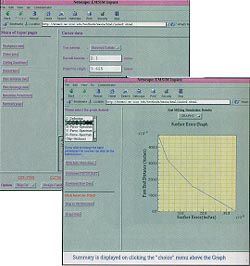
Figure 1: EMSIM users can input data about an endmilling operation (above) and receive accurate, graphical predictions about the process within seconds (right).
The corporations sponsoring the software’s development were very receptive to it, and the universities that participate in MTAMRI have used
EMSIM in their classrooms for several years. Othersbegan to take notice when it was made available to the public online. DeVor said that EMSIM is used approximately 6,000 times per year by job shops, manufacturing companies and colleges that aren’t affiliated with MTAMRI.
An EMSIM user enters the MTAMRI Web site and inputs data about his or her workpiece, cutting tools, cutting conditions and process faults, such as runout and flute breakage. EMSIM then simulates the machining process online and predicts cutting forces, surface-finish quality and dimensional accuracy (Figure 1).
EMSIM’s development has been followed by online simulators for drilling (DRSIM), fixture design (FIXMA) and cutting-fluid evaluation (CFEST). A turning simulator (TURNSIM) and a facemilling simulator (FMSIM) are under development and are expected to be online later this year.
Solving Specific Problems
The main benefit of the simulators is that they allow a user to find the best way to machine a part without producing a mound of scrap.
For instance, Ford Motor Co. wanted to facemill a complex transmission-valve body to a certain flatness. Engineers at Ford were trying to redesign the fixture that was holding the valve body, and they wanted a very accurate representation of what the cutting forces would be as the mill moved across the face of the part. FMSIM told Ford what the forces would be and how they would vary. The automaker then used the data to design the new fixture, and in the end, produce a flatter part.
Another company was experiencing problems endmilling a compressor part to precise tolerances. The part had extremely thin walls, so machining it was a challenge. The company wanted to be able to predict the cutting forces and a surface-error model for the part. EMSIM, along with finite-element analysis, provided the company with the information it needed to alter its process and meet the specified tolerances with acceptable levels of rejects.
“I think these are the things that really drive the research,” said DeVor. “You can sit in your office all day long and try to imagine what you ought to be doing, but when people come to you with problems like this and you can solve them, then you know you’re on the right track.”
Rick Baker, owner of Ponderosa Machine & Electronics in Albuquerque, N.M., recently discovered EMSIM while browsing online. He immediately used it for a job involving an aluminum housing for a customer in the electronics industry. Overall, he said that the software is excellent.
“One big advantage is that if you play around with the EMSIM software for a while, you get a much clearer understanding of the forces involved with milling,” said Baker. “That was not only valuable to me for that one job, but for all of the jobs that I run.”
But What’s the Real Problem?
The software testbeds have been extremely popular. However, they don’t provide guidance. A machinist working with one of the simulators could learn how well a given set of parameters will perform, but the software won’t tell him or her what parameters to tweak to achieve the best results.
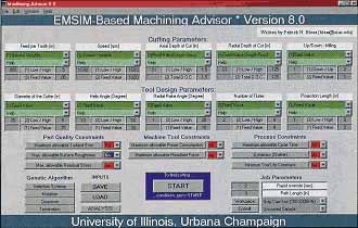
Figure 2: The Machining Advisor software testbed will allow users to determine optimal cutting conditions for a process based on the results required.
This is where UIUC’s EMSIM-based Machining Advisor software steps in. It allows users to optimize the machining process by offering a range of cutting conditions for a given set of performance standards (Figure 2). An endmilling model has already been developed and was made available to the program’s sponsors in May. Plans call for it be offered to the public in 2000. Additionally, a system for facemilling, based on FMSIM, is under development.
“I think some of our industrial sponsors will use [Machining Advisor] to try to fine-tune their processes,” said DeVor. “They want to squeeze some money out of their process by saying, ‘How hard can I push this cutting tool? How aggressive can I be and still meet the quality requirements?’”
All input variables are specified as search variables or fixed variables. For search variables, the user inputs the lowest and highest value allowed for each variable. Fixed variables require the input of specific values. The software also has a sensitivity-analysis feature, which allows the user to see which variables have a stronger effect on the process.
Once the variables are input, Machining Advisor conducts a series of virtual test runs and pinpoints the variables that produce the results closest to the specified requirements.
Virtual Research Takes Off
MTAMRI researchers have been encouraged by the response to their software testbeds. The success has led the participating universities to develop additional Internet-related projects, including a Virtual Machine Tool project and a hardware testbed.
The VMT project consists of software that will eventually allow users to evaluate possible machine tool designs online. Machine tool manufacturers, job shops and other users will be able to input parameters and determine an optimal machine tool configuration before building or purchasing a machine tool.
The Internet-based hardware testbed allows users to view an experiment taking place in a remote location, collect data in real time, then download graphs and other data for analysis.
The hardware testbed is still in the early stages of development, and the research is a collaborative effort that involves a number of universities. For instance, UIUC researchers recently ran an experiment that was viewed remotely by Professor John Sutherland and his students at Michigan Technological University, another MTAMRI participant.
“Down the road, we think this has several applications,” DeVor said of the hardware testbed. “It could be used as an educational tool or as a quality-control method to monitor suppliers from a remote location.”
The Bottom Line
All of the MTAMRI projects have received high praise from the program’s sponsors and partners. But the success of the program has not only been due to the dynamic capabilities of the Internet. According to DeVor, the strength of so many major industry players has allowed the program to flourish. He said that the companies involved are very excited about MTAMRI’s ideas and projects and are happy to participate.
“Most of the companies realize that for us to be successful in terms of educating students properly, their help is important,” said DeVor. “That’s one of our goals here—to advance knowledge and disseminate that knowledge. They understand that, and I guess we’ve also been able to provide the kinds of things that keep these companies coming back.”
Simulation software for grinding standard and special
Rollomatic Inc. recently introduced 3-D simulation software that boasts “special” capabilities. Developed to work in conjunction with the company’s 6-axis CNC600X tool-grinding machine, VirtualGrind/3D-Calc software allows the user to design and test programs to make standard and special tools on a PC before the tools are ground.
VirtualGrind provides a 3-D simulation of the tool-grinding process. The user can rotate the tool to view it from any angle, zoom in, pan out and magnify any part of the geometry.
According to Rollomatic’s president, Eric Schwarzenbach, his competitors’ products only simulate the grinding of standard cutting tools. Speaking from the company’s office in Mundelein, Ill., he added that VirtualGrind is free with the purchase of a CNC600X. Similar packages may cost up to $17,000.
VirtualGrind duplicates all of the functions and calculations made by the grinding machine’s Fanuc controller. Windows that appear on the user’s PC graphically represent the relative positions of the grinding wheels and the tool blank to be ground.
The 3-D simulation within VirtualGrind is based on ISO programming language (G and M codes). “In order to simulate tools from the ISO program, we had to create a proprietary syntax analysis,” explained Schwarzenbach. “This syntax analysis can recognize all Fanuc calculations, movements and logic patterns. The movements for the 3-D simulation of special tools are extracted from this analysis system.”
A “standards” window is used to simulate the grinding of standard tools. The designer imports data stored in the Fanuc controller that pertain to flutes, lands, points, chisel edges and other aspects of a tool’s geometry.
For a special tool, like a boring bar, the designer uses custom windows, said Schwarzenbach. After inputting parameters, the NC verification function simulates the setup and grinding process in three dimensions. The verification process helps guard against crashes occurring during the actual operation.
Schwarzenbach said that users’ response to VirtualGrind has been good and it is now being introduced in the U.S. market. He recommends the software for batch production.
“Simulation software is especially useful for small batches, because you don’t want to waste blanks,” he said. “A 1/8"-dia. ballnose carbide blank costs 40 cents, which isn’t a big deal. But a 5/8"-dia. blank costs $18, and if you waste 10 of them, you’re really losing money.”
—Don Nelson
Related Glossary Terms
- 3-D
3-D
Way of displaying real-world objects in a natural way by showing depth, height and width. This system uses the X, Y and Z axes.
- boring
boring
Enlarging a hole that already has been drilled or cored. Generally, it is an operation of truing the previously drilled hole with a single-point, lathe-type tool. Boring is essentially internal turning, in that usually a single-point cutting tool forms the internal shape. Some tools are available with two cutting edges to balance cutting forces.
- boring bar
boring bar
Essentially a cantilever beam that holds one or more cutting tools in position during a boring operation. Can be held stationary and moved axially while the workpiece revolves around it, or revolved and moved axially while the workpiece is held stationary, or a combination of these actions. Installed on milling, drilling and boring machines, as well as lathes and machining centers.
- endmilling
endmilling
Operation in which the cutter is mounted on the machine’s spindle rather than on an arbor. Commonly associated with facing operations on a milling machine.
- facemill
facemill
Milling cutter for cutting flat surfaces.
- facemilling
facemilling
Form of milling that produces a flat surface generally at right angles to the rotating axis of a cutter having teeth or inserts both on its periphery and on its end face.
- fixture
fixture
Device, often made in-house, that holds a specific workpiece. See jig; modular fixturing.
- flutes
flutes
Grooves and spaces in the body of a tool that permit chip removal from, and cutting-fluid application to, the point of cut.
- gang cutting ( milling)
gang cutting ( milling)
Machining with several cutters mounted on a single arbor, generally for simultaneous cutting.
- grinding
grinding
Machining operation in which material is removed from the workpiece by a powered abrasive wheel, stone, belt, paste, sheet, compound, slurry, etc. Takes various forms: surface grinding (creates flat and/or squared surfaces); cylindrical grinding (for external cylindrical and tapered shapes, fillets, undercuts, etc.); centerless grinding; chamfering; thread and form grinding; tool and cutter grinding; offhand grinding; lapping and polishing (grinding with extremely fine grits to create ultrasmooth surfaces); honing; and disc grinding.
- milling
milling
Machining operation in which metal or other material is removed by applying power to a rotating cutter. In vertical milling, the cutting tool is mounted vertically on the spindle. In horizontal milling, the cutting tool is mounted horizontally, either directly on the spindle or on an arbor. Horizontal milling is further broken down into conventional milling, where the cutter rotates opposite the direction of feed, or “up” into the workpiece; and climb milling, where the cutter rotates in the direction of feed, or “down” into the workpiece. Milling operations include plane or surface milling, endmilling, facemilling, angle milling, form milling and profiling.
- milling machine ( mill)
milling machine ( mill)
Runs endmills and arbor-mounted milling cutters. Features include a head with a spindle that drives the cutters; a column, knee and table that provide motion in the three Cartesian axes; and a base that supports the components and houses the cutting-fluid pump and reservoir. The work is mounted on the table and fed into the rotating cutter or endmill to accomplish the milling steps; vertical milling machines also feed endmills into the work by means of a spindle-mounted quill. Models range from small manual machines to big bed-type and duplex mills. All take one of three basic forms: vertical, horizontal or convertible horizontal/vertical. Vertical machines may be knee-type (the table is mounted on a knee that can be elevated) or bed-type (the table is securely supported and only moves horizontally). In general, horizontal machines are bigger and more powerful, while vertical machines are lighter but more versatile and easier to set up and operate.
- numerical control ( NC)
numerical control ( NC)
Any controlled equipment that allows an operator to program its movement by entering a series of coded numbers and symbols. See CNC, computer numerical control; DNC, direct numerical control.
- turning
turning
Workpiece is held in a chuck, mounted on a face plate or secured between centers and rotated while a cutting tool, normally a single-point tool, is fed into it along its periphery or across its end or face. Takes the form of straight turning (cutting along the periphery of the workpiece); taper turning (creating a taper); step turning (turning different-size diameters on the same work); chamfering (beveling an edge or shoulder); facing (cutting on an end); turning threads (usually external but can be internal); roughing (high-volume metal removal); and finishing (final light cuts). Performed on lathes, turning centers, chucking machines, automatic screw machines and similar machines.
- web
web
On a rotating tool, the portion of the tool body that joins the lands. Web is thicker at the shank end, relative to the point end, providing maximum torsional strength.
Author

Don Nelson served as publisher of Cutting Tool Engineering from January 2001 through May 2018.