Workholding involves much more than slapping a part in a vise or chuck and pushing the cycle-start button. Beyond the basics lies a whole universe of custom chucks, clamping systems, horizontal and vertical vises, and hydraulic, pneumatic and manual fixtures.
Any workholding project must consider the scope of the machining to be completed in a given setup. For instance, if you decide to rough and finish a part in the same chucking, can the machine tool hold the tolerances? Because metal moves when squeezed, heated and chilled, can you be sure the part won’t change shape after it’s removed from the workholding?
Workholding for turning is mainly done with chucks or fixture plates on chucks, and the workpiece is clamped on its internal or external features. Locating should be on a primary face for initial turning and on a machined face for subsequent operations.
The same applies to workholding for turning and milling. A part may be any shape, of course, but your first rule is to try and contain all machining to the area bounded by the part’s three primary locating points. This is always the rule whether you are turning or milling the part or turning the tool. The goal of workholding setups is stability because it minimizes workpiece vibration during the cut.
It’s OK to machine outside the clamp point lines as long as the areas are close to the clamps. Work supports are needed for large, flat parts or if the part’s periphery has arms or extensions.
Courtesy of J. Mason
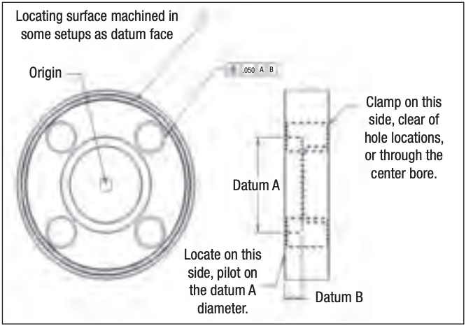
Geometric dimension and tolerancing for a part with four holes drilled around a center bore. Locating surface is machined in the same setup as the datum face. The part should be clamped on the turned face shown by crosshatch parallel to datum B and centered to datum A.
The nature of the workpiece material is another important consideration. If the workpiece material is forged or cast, the workholding arrangement should take into account the primary locating surfaces. Round and square bar stock offer good primary locating surfaces. Those are also found on premachined stock.
In addition to evaluating the mechanical features of a workholding setup, shops must also consider how part dimensions and the relationship of the geometrical elements necessary for part functionality, or “geometric dimension and tolerancing” (GD&T), will be affected by machining.
Let’s say you need to drill four holes around a center bore and achieve a tight hole tolerance and maintain a true position requirement to the bore “A” and a perpendicular requirement to datum face “B” as shown in the figure. Your first operation is turning, in which A and B are machined in the same setup. Drilling is next, in which the holes must be finished in relation to A and B. Normally, you would set the part down on datum B and center datum A for the origin.
However, the diameters of the holes’ positions are outside the diameter of datum B. If you clamp down on the ID datum face B, holding true position will be difficult because the part will want to tip out of position due to pressure from the drill. So don’t clamp to that feature.
If you turn a parallel face on the part outside the holes’ centerline locations during the same operation as when finishing the inside ID face, you can maintain the parallelism of the locating face to the datum callout and incorporate that into the workholding setup. This will keep the part stable and help meet the GD&T requirement for the holes to maintain their true position to the center bore.
GD&T can get tricky. Use this True Position Calculator to get the right numbers
Now that the workholding is correctly defined, it’s up to the machine and machinist to maintain positional accuracy and it’s up to the cutting tool to maintain size.
Good workholding is always the first step to making good parts.
Related Glossary Terms
- chuck
chuck
Workholding device that affixes to a mill, lathe or drill-press spindle. It holds a tool or workpiece by one end, allowing it to be rotated. May also be fitted to the machine table to hold a workpiece. Two or more adjustable jaws actually hold the tool or part. May be actuated manually, pneumatically, hydraulically or electrically. See collet.
- fixture
fixture
Device, often made in-house, that holds a specific workpiece. See jig; modular fixturing.
- flat ( screw flat)
flat ( screw flat)
Flat surface machined into the shank of a cutting tool for enhanced holding of the tool.
- gang cutting ( milling)
gang cutting ( milling)
Machining with several cutters mounted on a single arbor, generally for simultaneous cutting.
- inner diameter ( ID)
inner diameter ( ID)
Dimension that defines the inside diameter of a cavity or hole. See OD, outer diameter.
- milling
milling
Machining operation in which metal or other material is removed by applying power to a rotating cutter. In vertical milling, the cutting tool is mounted vertically on the spindle. In horizontal milling, the cutting tool is mounted horizontally, either directly on the spindle or on an arbor. Horizontal milling is further broken down into conventional milling, where the cutter rotates opposite the direction of feed, or “up” into the workpiece; and climb milling, where the cutter rotates in the direction of feed, or “down” into the workpiece. Milling operations include plane or surface milling, endmilling, facemilling, angle milling, form milling and profiling.
- parallel
parallel
Strip or block of precision-ground stock used to elevate a workpiece, while keeping it parallel to the worktable, to prevent cutter/table contact.
- tolerance
tolerance
Minimum and maximum amount a workpiece dimension is allowed to vary from a set standard and still be acceptable.
- turning
turning
Workpiece is held in a chuck, mounted on a face plate or secured between centers and rotated while a cutting tool, normally a single-point tool, is fed into it along its periphery or across its end or face. Takes the form of straight turning (cutting along the periphery of the workpiece); taper turning (creating a taper); step turning (turning different-size diameters on the same work); chamfering (beveling an edge or shoulder); facing (cutting on an end); turning threads (usually external but can be internal); roughing (high-volume metal removal); and finishing (final light cuts). Performed on lathes, turning centers, chucking machines, automatic screw machines and similar machines.
Author

Joe Mason is sales cost estimator for Schwartz Industries Inc., Warren, Mich. He has worked in the metalworking industry since 1978. Contact him at [email protected].
Joe Mason is cost estimator and process engineer for United Machining Inc., Sterling Heights, Mich., a supplier of high-heat manifold, turbine and exhaust components. Contact him at [email protected].