Defining chucks used for turning

Author Cutting Tool Engineering
Published
August 01, 2012 - 11:15am

For turning applications, there are many types of workholders. One is the chuck, a universal holding device capable of OD or ID clamping. It can be manually, pneumatically, hydraulically or electrically actuated.

Lathe chucks are mounted horizontally, vertically (facing up) or inverted (facing down). The chuck is bolted to a machine-mounted adapter plate. A drawtube is connected from the rear of the chuck, and the CNC or operator actuates the drawtube to clamp and unclamp the chuck. 

Figure1.tif

Figure2.tif

Figures 1 and 2. A 3-jaw OD chuck (top), and a 3-jaw ID chuck.

Workholding components, sometimes called top tooling, are mounted to the chuck face. (Top tooling components are sometimes, but not always, jaws.) The workpiece is placed in the center of the tooling, the drawbar is actuated and the part is clamped in a defined manner based on the type of chuck being used.

The jaws (or another type of top tooling) slide to and from the chuck centerline. There can be two to eight jaws, depending on part shape, configuration and clamping area available. Figure 1 is a typical 3-jaw OD chuck. 

When using a 3-jaw ID chuck (Figure 2), the part ID may or may not have been machined prior to setup. All chucking operations require a specifically designed process, because to function correctly the jaw diameter must closely match the part diameter.

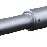
Figure 3 shows a part being held between centers that was previously machined on the ends. This allows the part to be completely turned in a single operation, which is common for finish turning and hard turning applications, such as turning shafts with tight tolerances from end to end. Turning between centers with face drivers requires a chuck, a driver mounted in the chuck and an opposing center for stability. 

Figure3.tif

Figure 3. A part being held between centers.

As with most workholders, specific chucking solutions for unique cutting requirements are custom-designed. For example, Jade Tool Inc., Traverse City, Mich., has been designing and building custom chucks for more than 20 years. Among other products, the company has developed pin chucks for roughing and finishing. The following examples are custom chucks designed by Jade Tool.

A pin chuck (Figure 4) pulls the part against the stop face (end stop) and has jaws that rock side to side to ensure secure six-point contact on the part, even if it is out of round.

Figure4.tif

Figure 4. A pin chuck.

A collet chuck (Figure 5) can be an ID or OD gripping chuck. It grips with either a pullback action to help pull the part against the end stop or a static grip for thinner parts that may be distorted by the pullback action.

A diaphragm chuck (Figure 6) can also be an ID or OD gripping chuck. It is normally used for finish machining, grinding or inspection. Because of its low-profile jaws and built-in chip slots, it can also be used for milling.

Figure5.tif

Figure5.tif

Figure 5. A collet chuck can be an ID or an OD gripping chuck. The chuck on the top is an ID clamping chuck with stops on the back plate, and the lower chuck has custom stops for a specific part.

Jade Tool also offers a “soft-touch” chuck (Figure 7), which can be an ID or OD gripping chuck as well. This chuck, which uses jaws, centers and supports a part around its entire ID or OD and has a patented design to hold thin-wall parts without distorting them. Thin-wall parts are a growing challenge because they are being used more frequently in automotive components to reduce weight.

How a part is clamped is directly related to the print that defines the part’s most important features and how those features are related.

Figure6.tif

Figure7.tif

Figures 6 and 7. A diaphragm chuck (top), and a “soft-touch” chuck.

Cast or forged round parts should have a machine start dimension taken from the primary datums. If primary datums are not designated, then a review of the part finish requirements determines the required initial and subsequent finish workholding.

In most circumstances where the part’s OD, ID and ends require finishing, turning consists of roughing and finishing. But sometimes only one of these turning operations is necessary.

The part print defines the locating scheme and subsequent chucking requirement. The part’s geometrical tolerances on the finishing print will complete the workholding plan. It is extremely important to understand the required tolerances, especially when finishing part features in multiple operations or setups. CTE

About the Author: Joe Mason is cost estimator and process engineer for United Machining Inc., Sterling Heights, Mich. He has worked in the metalworking industry since 1978. Contact him at cncgcode@earthlink.net.

Related Glossary Terms

  • centers

    centers

    Cone-shaped pins that support a workpiece by one or two ends during machining. The centers fit into holes drilled in the workpiece ends. Centers that turn with the workpiece are called “live” centers; those that do not are called “dead” centers.

  • chuck

    chuck

    Workholding device that affixes to a mill, lathe or drill-press spindle. It holds a tool or workpiece by one end, allowing it to be rotated. May also be fitted to the machine table to hold a workpiece. Two or more adjustable jaws actually hold the tool or part. May be actuated manually, pneumatically, hydraulically or electrically. See collet.

  • collet

    collet

    Flexible-sided device that secures a tool or workpiece. Similar in function to a chuck, but can accommodate only a narrow size range. Typically provides greater gripping force and precision than a chuck. See chuck.

  • computer numerical control ( CNC)

    computer numerical control ( CNC)

    Microprocessor-based controller dedicated to a machine tool that permits the creation or modification of parts. Programmed numerical control activates the machine’s servos and spindle drives and controls the various machining operations. See DNC, direct numerical control; NC, numerical control.

  • gang cutting ( milling)

    gang cutting ( milling)

    Machining with several cutters mounted on a single arbor, generally for simultaneous cutting.

  • grinding

    grinding

    Machining operation in which material is removed from the workpiece by a powered abrasive wheel, stone, belt, paste, sheet, compound, slurry, etc. Takes various forms: surface grinding (creates flat and/or squared surfaces); cylindrical grinding (for external cylindrical and tapered shapes, fillets, undercuts, etc.); centerless grinding; chamfering; thread and form grinding; tool and cutter grinding; offhand grinding; lapping and polishing (grinding with extremely fine grits to create ultrasmooth surfaces); honing; and disc grinding.

  • hard turning

    hard turning

    Single-point cutting of a workpiece that has a hardness value higher than 45 HRC.

  • inner diameter ( ID)

    inner diameter ( ID)

    Dimension that defines the inside diameter of a cavity or hole. See OD, outer diameter.

  • lathe

    lathe

    Turning machine capable of sawing, milling, grinding, gear-cutting, drilling, reaming, boring, threading, facing, chamfering, grooving, knurling, spinning, parting, necking, taper-cutting, and cam- and eccentric-cutting, as well as step- and straight-turning. Comes in a variety of forms, ranging from manual to semiautomatic to fully automatic, with major types being engine lathes, turning and contouring lathes, turret lathes and numerical-control lathes. The engine lathe consists of a headstock and spindle, tailstock, bed, carriage (complete with apron) and cross slides. Features include gear- (speed) and feed-selector levers, toolpost, compound rest, lead screw and reversing lead screw, threading dial and rapid-traverse lever. Special lathe types include through-the-spindle, camshaft and crankshaft, brake drum and rotor, spinning and gun-barrel machines. Toolroom and bench lathes are used for precision work; the former for tool-and-die work and similar tasks, the latter for small workpieces (instruments, watches), normally without a power feed. Models are typically designated according to their “swing,” or the largest-diameter workpiece that can be rotated; bed length, or the distance between centers; and horsepower generated. See turning machine.

  • metalworking

    metalworking

    Any manufacturing process in which metal is processed or machined such that the workpiece is given a new shape. Broadly defined, the term includes processes such as design and layout, heat-treating, material handling and inspection.

  • milling

    milling

    Machining operation in which metal or other material is removed by applying power to a rotating cutter. In vertical milling, the cutting tool is mounted vertically on the spindle. In horizontal milling, the cutting tool is mounted horizontally, either directly on the spindle or on an arbor. Horizontal milling is further broken down into conventional milling, where the cutter rotates opposite the direction of feed, or “up” into the workpiece; and climb milling, where the cutter rotates in the direction of feed, or “down” into the workpiece. Milling operations include plane or surface milling, endmilling, facemilling, angle milling, form milling and profiling.

  • outer diameter ( OD)

    outer diameter ( OD)

    Dimension that defines the exterior diameter of a cylindrical or round part. See ID, inner diameter.

  • turning

    turning

    Workpiece is held in a chuck, mounted on a face plate or secured between centers and rotated while a cutting tool, normally a single-point tool, is fed into it along its periphery or across its end or face. Takes the form of straight turning (cutting along the periphery of the workpiece); taper turning (creating a taper); step turning (turning different-size diameters on the same work); chamfering (beveling an edge or shoulder); facing (cutting on an end); turning threads (usually external but can be internal); roughing (high-volume metal removal); and finishing (final light cuts). Performed on lathes, turning centers, chucking machines, automatic screw machines and similar machines.