New, ultraresilient workpiece materials with high strength-to-weight ratios have cutting tool vendors and CAM developers scrambling to design new tools and toolpaths to efficiently cut them. To succeed, the vendors and developers must collaborate with unprecedented frequency.
These interactions range from simple information requests to lengthy projects involving teams of specialists. The vendors and developers do the work while parts manufacturers reap the benefits of increased efficiency and cost reductions. Following are some examples.
Taming Inconel: Inconel is notoriously difficult to cut, but it isn’t really “cut” at all. The cutter geometry, at elevated surface speeds, generates enough heat to turn the material into a plasma. The gummy, abrasive material can then be flung from the cutter’s flutes. Normal cutting strategies call for conservative feed rates with slight step-overs and step-downs. Material-removal rates are low. Tools wear quickly.
Kennametal Inc., Latrobe, Pa., introduced a ceramic endmill to cut Inconel with greater efficiency and less tool wear. The toolmaker’s engineers were confident their tool would produce good results when paired with CAM software that could consistently maintain the desired chip loads.
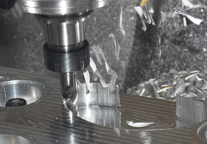
CAM software developers and tool manufacturers work closely together to help ensure new toolpath technology adheres to a toolmaker’s optimal chip-load recommendations. Image courtesy of CNC Software.
They approached CNC Software Inc. (developers of Mastercam CAD/CAM software), which assigned an applications engineer to create an optimized program for cutting Inconel. The engineer designed the test part and developed programs for the new cutting tool. Using the technology to maintain consistent cutting action, he pushed feeds and speeds to the limit of safe cutting parameters.
Normally in this situation, an end user would change a carbide endmill after about 10 minutes of cutting. The new design held for 20 minutes. Material-removal efficiency was improved considerably. At CNC Software’s manufacturing lab, the tool vendor learned how to advise customers about the best ways to use this new design.
Qualifying Tools and Building Libraries: A turnkey applications engineer from toolmaker RobbJack Corp., Lincoln, Calif., learned at the lab about constant-chip-load programming with Mastercam. He optimized and confirmed cutting parameters by performing test cuts using 30 different endmills.
Once users have obtained optimal cutting parameters, they can capture that information in the CAM software’s cutting tool libraries, a powerful tool for improving machining effectiveness. Vendors and developers sometimes collaborate to capture these parameters, helping CNC shops machine more effectively.
Iscar Metals Inc., Arlington, Texas, and CNC Software are building HEM (high-efficiency machining) libraries that incorporate Iscar’s line of solid-carbide endmills and Mastercam’s Dynamic Motion toolpaths. Proprietary formulas combined with specified values from the library adjust the speeds and feeds to maintain an ideal chip load. These formula-driven values provide sufficient heat removal when the cutter is operating at small step-overs (25 percent or less of the tool diameter) or deep step-downs (generally 2 to 2.5 times the cutting diameter and up to 4 times the diameter). This cost-effective strategy improves material-removal efficiency and tool life.
Reducing Ceramic Button Insert Notching: These inserts are often applied when turning superalloys. The inserts are very hard and prone to vibration, notch easily and have limited tool life, partly due to the material’s properties, the forces involved and wear-pattern issues that arise when following standard linear toolpaths.
Partnering with Sandvik Coromant Co., Fair Lawn, N.J., Mastercam engineers developed a Dynamic Motion toolpath to provide nonlinear motion that would distribute the wear pattern over a broad surface area of the insert. Sandvik Coromant tested the prototype toolpath, which reduced tool wear, reduced air cutting, shortened cycle times and improved overall turning efficiency. It also enhanced chip breaking and reduced vibration.
Shaped Tools: In recent years, CAM software developers and tool manufacturers have collaborated to assure that new toolpath technologies adhere to toolmakers’ optimal chip-load recommendations for advanced carbide cutting tools. This allows users to simply dial in the best-case mrr. The software’s material-aware algorithms automatically adjust tool motion to reach optimal performance. Adopters of this strategy routinely report material-removal improvements of 25 percent or better.
Software and tool designers now aim for similar improvements for finishing cycles. They recommend applying shaped cutting tools that, as the software rotates them, conform better to the surface being machined.
For example, CNC Software partnered with Emuge Corp., West Boylston, Mass., to provide tool-specific cutting motions for Emuge’s Circle Segment finishing tools. Ball endmills have long been the go-to tools for finishing. To eliminate the “staircase effect” on a part’s surface, a ball endmill contacts only a small portion of the surface due to the typical step-down and step-over distances. Therefore, large numbers of passes are required to completely finish a surface.
Circle Segment tools provide an effective cutting radius far greater than a ball endmill. The number of passes can be reduced significantly, shortening machining cycle times by up to 80 percent. Surface quality is improved because cusps are shallower and more widely spaced.
Increased contacts between vendors and CAM developers promote innovative technical exchanges. The new toolpath strategies have led customers to high productivity gains. The advantages for smaller step-overs can also apply to heavy step-overs of 65 to 80 percent, with even higher removal rates.
Related Glossary Terms
- abrasive
abrasive
Substance used for grinding, honing, lapping, superfinishing and polishing. Examples include garnet, emery, corundum, silicon carbide, cubic boron nitride and diamond in various grit sizes.
- computer numerical control ( CNC)
computer numerical control ( CNC)
Microprocessor-based controller dedicated to a machine tool that permits the creation or modification of parts. Programmed numerical control activates the machine’s servos and spindle drives and controls the various machining operations. See DNC, direct numerical control; NC, numerical control.
- computer-aided manufacturing ( CAM)
computer-aided manufacturing ( CAM)
Use of computers to control machining and manufacturing processes.
- endmill
endmill
Milling cutter held by its shank that cuts on its periphery and, if so configured, on its free end. Takes a variety of shapes (single- and double-end, roughing, ballnose and cup-end) and sizes (stub, medium, long and extra-long). Also comes with differing numbers of flutes.
- feed
feed
Rate of change of position of the tool as a whole, relative to the workpiece while cutting.
- flutes
flutes
Grooves and spaces in the body of a tool that permit chip removal from, and cutting-fluid application to, the point of cut.
- step-over
step-over
Distance between the passes of the toolpath; the path spacing. The distance the tool will move horizontally when making the next pass. Too great of a step-over will cause difficulty machining because there will be too much pressure on the tool as it is trying to cut with too much of its surface area.
- superalloys
superalloys
Tough, difficult-to-machine alloys; includes Hastelloy, Inconel and Monel. Many are nickel-base metals.
- toolpath( cutter path)
toolpath( cutter path)
2-D or 3-D path generated by program code or a CAM system and followed by tool when machining a part.
- turning
turning
Workpiece is held in a chuck, mounted on a face plate or secured between centers and rotated while a cutting tool, normally a single-point tool, is fed into it along its periphery or across its end or face. Takes the form of straight turning (cutting along the periphery of the workpiece); taper turning (creating a taper); step turning (turning different-size diameters on the same work); chamfering (beveling an edge or shoulder); facing (cutting on an end); turning threads (usually external but can be internal); roughing (high-volume metal removal); and finishing (final light cuts). Performed on lathes, turning centers, chucking machines, automatic screw machines and similar machines.
Author
 |
 |
Stas Mylek (left) is senior applications adviser and Jesse Trinque is applications engineer for CNC Software Inc., Tolland, Conn. For more information about the company’s Mastercam CAD/CAM software, call (800) 228-2877 or visit www.mastercam.com.