Thanks to modern machine-control technology, milling cutters are lasting longer and performing better than ever at higher speeds and feeds.
 |
|
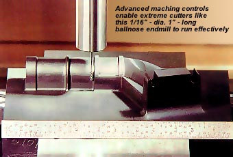
| Advanced machine controls enable extreme cutters like this 1¼16"-dia., 1"-long ballnose endmill to run effectively. | |
Improved milling-cutter performance can help shops run their CNC machines at higher speeds and feeds without sacrificing part accuracy. More, lighter passes can be taken to keep the heat out of the part and the cutter to improve surface finish while decreasing cycle time. Shops can achieve faster delivery, higher productivity, and greater accuracy—provided that their machine controls give them adequate control over the cutting edge to handle light passes at high speeds and feeds.
Due to limitations of older controls, most CNC machines cannot perform efficiently at the parameters necessary for high-speed milling. Operators of these machines often compromise the optimal cutting conditions in an effort to gain productivity. The results of making deeper cuts at slower feed rates include heat transfer to the part and the cutter, less accuracy, and premature cutter wear.
Changes in feed rates are the biggest obstacle to success in high-speed milling and all other chipmaking applications. Feed rates are influenced by the data flow, CNC performance, drive performance, and machine dynamics. The most significant advancements over the last decade have been made in the flow of data from the CAD/CAM system to the CNC and in the speed and accuracy of the CNC.
There are two components to the data flow. When milling complex parts, part programs may have to be fed to the machine from an external source, since the CNC’s memory may not be able to store all the data. Direct numerical control (DNC) is often necessary to store these large programs. The DNC sends the data from a computer to the CNC. The CNC then interprets the data and issues the commands to the drive system. Either the flow of data to the CNC or the flow of data through the CNC can hinder the implementation of high-speed milling.
DNC Data Flow
Many CNC milling applications rely on a constant transfer of data from the DNC to the CNC. The DNC system can be a bottleneck if the data can’t flow fast enough for the CNC to achieve the high feed rate that has been specified.
CNC programs for complex parts, such as molds and aerospace components, contain large amounts of data. These lengthy programs generate a 3-D shape by making thousands of very tiny motions. A typical program block in a DNC file will contain two or more axes of command data. A block may look something like this:
G1 X123.456 Z234.567
Even invisible characters like the spaces, carriage return, and line feed all are characters that take time to transmit. Each program block averages approximately 20 characters in length. The block will be longer if it contains 3-axis information, or if line numbers and feed rates are stated.
For coarse programs running at slow feed rates, most CNCs can easily keep up with the data-transfer rate from the DNC. However, as the feed rate is increased, it becomes harder for the CNC to keep up with the transfer rate. In many cases, the CNC won’t be able to run at the desired feed rate.
Consider a series of points nominally 0.010" apart that describe a complex 3-D surface. To achieve a feed rate of 150 ipm, 15,000 blocks of program data have to run through the DNC in 1 minute. If each block is 20 characters long, the DNC has to be able to run at 300,000 characters per minute, or 5000 characters per second. Since most DNCs are only capable of running at 960 characters per second, the CNC won’t even come close to achieving a feed rate of 150 ipm.
 |
(A) | |
 |
(B) | |
| (C) | ||
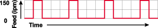
| Figure 1: Machine performance due to data starvation through DNC at 100% of programmed feed rate (A), 50% (B), and 25% (C).
Courtesy of Creative Technology Corp. |
||
In many high-speed milling applications, the demand for data far outstrips the ability of the DNC system to provide that data. Therefore, the CNC machine has to run what data it has, stop and wait until it gets more, run what it gets, stop and wait for more, and so on through the part. These starts and stops change the feed rate. Figure 1A represents this “stuttering” machine performance caused by data starvation.
During each change in feed rate to start and stop, the cutting edges are damaged by the changing chipload. The momentary rubbing of the cutter against the part may workharden the workpiece material, leading to further damage to the cutter.
To optimize the performance of the machine and the tool, the operator will normally use the machine’s feed override to slow the feed rate to a point where the motion is smooth. The results are shown in Figures 1B and 1C. If the operator reduces the programmed feed by 50%, the machine runs more of the time than at 100%. If the feed is again halved to just 25% of the programmed feed, the motion is smooth and continuous. There is no loss in machine performance to move the same distance, provided that the DNC is the problem. Of course, by slowing down, the advantages of high-speed milling are lost.
Luckily, many controls are now working at higher baud rates to transfer the CNC program faster by DNC. Generally speaking, the higher the baud rate, the faster the transfer rate. A baud rate of 9600 allows a throughput of up to 960 characters per second. Baud rates of 38,400, and even 115,200, are reducing the problems posed by DNC. But it is important to remember that denser data require still higher throughputs. Furthermore, the actual throughput of any DNC system is seldom near its theoretical potential. DNC systems are often working too near their saturation point to provide acceptable results with dense 3-D data.
A better solution to the data-throughput problem is direct CNC networking (DCN). Common Ethernet interfaces allow data to flow at the equivalent of up to 10,000,000 baud, resulting in a theoretical throughput of up to 1,000,000 characters per second. This is 1000 times faster than most DNC systems. Many older controls are not capable of DCN. Many newer controls can implement DCN for less money than DNC, provided that the user already has a network infrastructure set up.
However, the DNC isn’t the only bottleneck in the data flow. Even if the data can get to the CNC, many CNCs can’t keep up with the data. Realizing the benefits of high-speed milling requires fast and accurate CNCs capable of handling data at high speeds and feeds.
CNC Data Flow
The CNC’s block-transfer time is a common limitation in data flow. Because of design constraints, many CNCs can only handle a limited amount of data at a time. For the previous example of 15,000 blocks per minute, a CNC would have to execute 250 blocks per second, or have a block-transfer time of less than 4 milliseconds. While this capability is becoming more common, not all modern CNCs can handle that rate of data flow. Most CNCs more than a couple of years old are simply not capable of dealing with 250 program blocks in 1 second.
Worse yet, the specification for block-transfer time can be quite confusing and misleading. Some of the fastest CNCs in the market today are touting capabilities of 1000 blocks per second, or a block-transfer time of 1 millisecond. This specification is based on short incremental moves on a single axis, not complex 3-D moves. Using such a specification is meaningless and deceptive, for no one would really want to make a straight line on one axis by a series of short moves. Rather, all the short moves would be combined into one long, continuous move.
Faster block-transfer times are available on a few CNCs today, and in some cases, these newer controls will cover simultaneous multiaxis moves. As faster CNCs become the norm, faster block-transfer times will help more CNCs allow fluid machining of complex geometries made up of dense 3-D data.
The results may appear the same regardless of the problem—either data starvation from the DNC or slow block-transfer-time performance from the CNC. If the machine is suffering from poor performance running long, dense programs, the operator can easily determine if the CNC’s block-transfer time is the bottleneck simply by loading a short but dense series of moves into the CNC’s memory. If the CNC runs acceptably from its own memory, the problem is the DNC. If the CNC won’t run satisfactorily from its own memory, better DNC performance simply won’t help.
CNC precision is another key to successful high-speed milling. Going fast in a fluid motion may give better cutter performance, but that benefit will be voided if the tool path isn’t executed accurately.
CNC Accuracy
Many fast CNCs on the market today can’t effectively perform high-speed milling because they lack the intelligence to “look ahead” at the tool path and anticipate its directional changes. They also may not check positioning integrity as often as required to accurately perform at the desired speeds. This can result in gouges, overshoots, and general inconsistencies with the program data.
Look-ahead is a fairly new feature found in only a few CNCs. Look-ahead has evolved from a need to prevent gouges while milling from point to point in rapid succession. When NC and CNC were first developed, data was executed one block at a time. Typical uses were drilling, tapping, and linear milling. Circular milling evolved over time. The big advantage to NC and CNC was that all moves were planned in advance and could happen much faster than a manual operator could execute the individual moves on the shop floor.
With the success of CAD/CAM, CNC has been used with increasing success to develop 3-D surface contours. In these applications, the cutter must flow through the points without dwelling as tools on older NC and CNC machines did. Most CNC milling machines take from 0.100" to 0.200" to stop from a move at 100 ipm. If a CNC machine is instructed to flow through data at high feed rates, yet point departures are short, gouges can result at points of abrupt changes in the contour.
 |
(A) | |
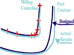 |
(B) | |
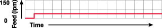
| Figure 2: A part with points sorted by chordal deviation (A) , and a close-up of the same part showing dangerous curves for overshoot without look-ahead (B).
Courtesy of Creative Technology Corp. |
||
The shape in Figure 2A shows several close data segments at the bottom of a contour. This is an area of great danger for gouging. The longer line segments going from left to right might easily permit high feed rates. As seen in Figure 2B, without look-ahead, the CNC might be surprised by the abrupt change in direction over a short move of only 0.010". If the feed rate is too high to stop in that distance, the result will be an overshoot. The centerline of the tool will miss its projected path, resulting in a gouge in the part.
Look-ahead must evaluate data many blocks ahead to prevent gouges. In most applications, look-ahead of one or two or even 10 or 20 blocks is not enough. The amount needed varies based on contours, feed rates, and machine performance. In general, look-ahead cannot be limited to any arbitrary value, because conditions are constantly changing. Ideally, look-ahead should be dynamic, varying the distance and number of program blocks based on the part profile and the desired milling feed rate.
CNC Speed
The speed of the CNC is just as critical as its accuracy. To realize gains in milling productivity, the machine must have a CNC capable of fast servo cycle times.
Servo cycle time is the amount of time a CNC takes for each measuring and command cycle. For example, if the CNC’s servo cycle time is 20 milliseconds, the axis positions are measured and the CNC commands a new direction 50 times a second. Though servo cycle times of 20 milliseconds were thought to be good just 10 years ago, servo cycle times greater than 4 milliseconds are now considered inadequate.
At a fairly common servo cycle time of 3 milliseconds, positions are being measured and corrected 333 times per second. A machine moving at 100 ipm is moving 1.66 in./sec., so each time the axes are measured the machine has moved 0.0050". This might be alarming to an operator trying to hold tolerances to 0.0001" or so, since the machine is basically out of control for 0.0050" increments at a time.
The accuracy problem gets worse when attempting to mill at 400 ipm, where a servo cycle time of 3 milliseconds results in 0.0200" moves between measurement and correction commands from the CNC. Such moves make it even more difficult to hold to close tolerances over contoured surfaces.
Table 1: Distance (in inches) moved at given feed rates and servo cycles. |
||||||||||||||||||||||||||||||||||||
Table 1 shows distances moved at various servo cycle times and feed rates. The importance of fast servo cycle times becomes quite obvious. The faster the desired milling feed rate, the faster the servo cycle time must be. Years ago, rapid-traverse rates were increased to 400 ipm, then 800 ipm, and now they’re even faster. Machinists couldn’t dream of milling accurately at those feed rates, though, because of the slower CNCs. The machines could withstand the stresses of quickly moving from one point to the next, but they lacked the accuracy required for such high feed rates.
Feed rates will continue to increase, and the need for faster servo cycle times will continue to grow. High-speed spindles, high-performance cutters, and advanced toolholders are proving capable of supporting very high speeds and feeds. Machines with linear motors are now available with traverse rates to 3000 ipm and more; they can accelerate to 3000 ipm faster than most machines today can get to 300 ipm. Fast servo cycle times will be a major consideration for milling fast with accuracy.
More Constant Feeds
For the majority of high-speed milling applications, it is impossible to maintain a constant feed rate and chipload. However, machinists can gain most of the benefits of high-speed milling by maintaining more constant feed rates. Basically, this involves eliminating dwells and minimizing changes in feed rate.
 |
(A) | |
 |
(B) | |
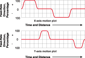
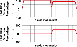
| Figure 3: A simple 4"53" rectangle (A) and a plot of drive performance for milling that shape (B).
Courtesy of Creative Technology Corp. |
||
Figure 3A illustrates the milling of a simple rectangular shape. A graphical plot of the machine’s drive performance might look like Figure 3B. A significant amount of the time milling the part is spent in dwells at the corners and in acceleration and deceleration. Minimizing that time will result in longer tool life and better milling productivity.
The CNC can minimize the dwells. Both the drive system and the CNC determine the acceleration and deceleration. Assuming that the drive performance is fixed, the CNC will make a difference in acceleration and deceleration by graphical drive tuning to extract peak performance from the drive system without strain on the drives or machine and without inaccuracies.
The problem is the scuffing of the cutting edges when they’re not fully engaging the material to be cut. During dwells, the rubbing that occurs simply heats the material to be cut and wears the cutting edge. Early in the acceleration curve, a slight amount of push occurs, but the cutter is deflected rather than engaged in the material. This builds heat and wears the cutting edges even more. Then the cutter breaks through and begins to really cut, but conditions are still less than optimal. Most of the stress is taken directly on the weakest point, the very cutting edge, because of the minimal penetration of the material. As the cutter more completely engages the material, the conditions improve and the cutter gains efficiency, but the damage has been done. The cutter is weakened.
 |
(A) | |
|
|
||
 |
(B) | |
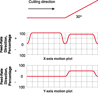
| Figure 4: A 30° drive plot using a conventional CNC (A)and the same plot using an intelligent, high-performance CNC (B).
Courtesy of Creative Technology Corp. |
||
Simply put, carbide likes pressure. By minimizing the dwells and reducing the time spent accelerating and decelerating, more constant feed rates will extend the life of carbide (and other) cutters and increase productivity. Consider the accelerations for a simple 30° angle in the x- and y-axes. First look at the contour in Figure 4A, cut on a machine with a common CNC built circa 1990. Notice the complete stop at the intersection. Now look at the same contour in Figure 4B, cut with the latest of CNCs, using higher acceleration and the intelligence to analyze the corner for minimum delay. The result is a much more constant feed rate through the part.
Throughout the part, the cutting edge slowly degrades, except through the dwells and the acceleration and deceleration areas where the faster wear and greater number of failures occur. Minimizing the time in these areas can dramatically extend cutter life.
Longer tool life, better cutter performance, and other benefits of high-speed milling can only be realized if the machine provides optimal control of the cutting edge. By incorporating modern control technology, today’s machines can achieve consistently higher levels of accuracy and efficiency than previously were possible.
About the Author
Todd Schuett is president of Creative Technology Corp., Arlington Heights, IL.
Related Glossary Terms
- 3-D
3-D
Way of displaying real-world objects in a natural way by showing depth, height and width. This system uses the X, Y and Z axes.
- computer numerical control ( CNC)
computer numerical control ( CNC)
Microprocessor-based controller dedicated to a machine tool that permits the creation or modification of parts. Programmed numerical control activates the machine’s servos and spindle drives and controls the various machining operations. See DNC, direct numerical control; NC, numerical control.
- direct numerical control ( DNC)
direct numerical control ( DNC)
Method of transferring CNC code from the CAD/CAM system to the machine tool.
- direct numerical control ( DNC)2
direct numerical control ( DNC)
Method of transferring CNC code from the CAD/CAM system to the machine tool.
- endmill
endmill
Milling cutter held by its shank that cuts on its periphery and, if so configured, on its free end. Takes a variety of shapes (single- and double-end, roughing, ballnose and cup-end) and sizes (stub, medium, long and extra-long). Also comes with differing numbers of flutes.
- feed
feed
Rate of change of position of the tool as a whole, relative to the workpiece while cutting.
- gang cutting ( milling)
gang cutting ( milling)
Machining with several cutters mounted on a single arbor, generally for simultaneous cutting.
- inches per minute ( ipm)
inches per minute ( ipm)
Value that refers to how far the workpiece or cutter advances linearly in 1 minute, defined as: ipm = ipt 5 number of effective teeth 5 rpm. Also known as the table feed or machine feed.
- look-ahead
look-ahead
CNC feature that evaluates many data blocks ahead of the cutting tool’s location to adjust the machining parameters to prevent gouges. This occurs when the feed rate is too high to stop the cutting tool within the required distance, resulting in an overshoot of the tool’s projected path. Ideally, look-ahead should be dynamic, varying the distance and number of program blocks based on the part profile and the desired feed rate.
- milling
milling
Machining operation in which metal or other material is removed by applying power to a rotating cutter. In vertical milling, the cutting tool is mounted vertically on the spindle. In horizontal milling, the cutting tool is mounted horizontally, either directly on the spindle or on an arbor. Horizontal milling is further broken down into conventional milling, where the cutter rotates opposite the direction of feed, or “up” into the workpiece; and climb milling, where the cutter rotates in the direction of feed, or “down” into the workpiece. Milling operations include plane or surface milling, endmilling, facemilling, angle milling, form milling and profiling.
- milling machine ( mill)
milling machine ( mill)
Runs endmills and arbor-mounted milling cutters. Features include a head with a spindle that drives the cutters; a column, knee and table that provide motion in the three Cartesian axes; and a base that supports the components and houses the cutting-fluid pump and reservoir. The work is mounted on the table and fed into the rotating cutter or endmill to accomplish the milling steps; vertical milling machines also feed endmills into the work by means of a spindle-mounted quill. Models range from small manual machines to big bed-type and duplex mills. All take one of three basic forms: vertical, horizontal or convertible horizontal/vertical. Vertical machines may be knee-type (the table is mounted on a knee that can be elevated) or bed-type (the table is securely supported and only moves horizontally). In general, horizontal machines are bigger and more powerful, while vertical machines are lighter but more versatile and easier to set up and operate.
- numerical control ( NC)
numerical control ( NC)
Any controlled equipment that allows an operator to program its movement by entering a series of coded numbers and symbols. See CNC, computer numerical control; DNC, direct numerical control.
- numerical control ( NC)2
numerical control ( NC)
Any controlled equipment that allows an operator to program its movement by entering a series of coded numbers and symbols. See CNC, computer numerical control; DNC, direct numerical control.
- overshoot
overshoot
Deviation from nominal path caused by momentum carried over from previous step, as when a tool is rapidly traversed a considerable distance to begin a cut. Usually applies to CNC machining and is prevented if the control has the appropriate look-ahead capability. See look-ahead; undershoot.
- tapping
tapping
Machining operation in which a tap, with teeth on its periphery, cuts internal threads in a predrilled hole having a smaller diameter than the tap diameter. Threads are formed by a combined rotary and axial-relative motion between tap and workpiece. See tap.