Presented here is the second part of a two-part series of columns about the importance of becoming familiar with CNC programming code. The following describes the steps involved in manually writing a program.
First, begin and end all programs with a percent sign (%), which tells the controller where a program starts and finishes. Then, insert a program number and follow it with a description of the part and setup number in parentheses, such as O00101 (adapter plate setup #1). Program numbers start with the letter O followed by a five-digit number. The program numbers can be whatever you choose. The controller ignores anything in parentheses, so the information inside parentheses is for your benefit only.


The X and Y starting point, or G54, is set roughly to the center of the part in the sample program. Image courtesy J. Harvey.
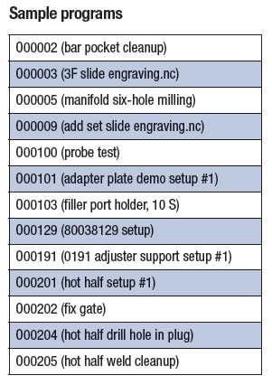
Program numbers help the controller keep track of stored programs. Each program stored in the controller has a different program number. The table lists sample program numbers.
Insert your safety line coding so the program runs as intended. Some codes erase commands in the controller’s memory that could cause a program to stop running. Your controller is likely set up with a number of defaults, which would make some—if not all—of these codes redundant and unnecessary.
However, having a strong safety line at the beginning of programs gives you peace of mind, because you know programs are going to start consistently. Furthermore, there is no execution time associated with using them. The following are some examples.
- G17 (XY plane)
- G20 (inch)
- G40 (cancel cutter compensation)
- G49 (cancel tool length compensation)
- G54 (start point)
- G80 (cancel canned cycles)
- G90 (absolute mode)
- G98 (initial plane for canned cycles)
- G90 (“absolute” mode) means all cutter positions in the program are measured from the G54 starting point. In this example, G54 is set to the center of the part.
Your post-processor, which is the software that spits out the code for a particular machine, can be set up to output whatever safety code you prefer. Next, call up a tool number, insert a tool-change command and follow with a description of the tool in parentheses, such as T1 M06 (#3 center drill). T1 is the center drill that will be installed and M6 is the command that tells the machine to go ahead and install the tool. M06 functions the same as M6. In other words, the zero between M and 6 is meaningless. Similarly, T01 functions the same as T1.
Insert a spindle speed and turn the spindle on. For example, S2000 sets the spindle rpm to 2,000, M3 is the command that turns the spindle clockwise and M4 is for turning the spindle counterclockwise.
Insert a “rapid” command and a starting-point command. Then, tell the spindle where to go in X and Y. For example, G0 G54 X0 Y0. G0 tells the machine to move fast. On our machines, the default rapid speed is 400 ipm when used at the 100 percent setting. We can override the rapid speed using the percentage buttons on the control panel. When testing a new program, the rapid speed can, and should be, overridden to a slower rate.
G54 is the zero starting point from which all X, Y and Z moves refer. In this case, I set the X and Y starting point to the approximate center of the part by locating the center with a pointer.
There is extra stock on the sides to be removed, so the starting point in X and Y does not have to be precisely accurate. The pointer position is then input into the work offset screen in the G54 register for X and Y. If more accuracy is needed for setting the starting point, an edge finder, an indicator or an electronic probe could be used.
I could have chosen a different starting point, but having the starting point at the center of the stock makes following the moves in this program easier.
If the starting point gets screwed up for any reason, you’ll likely end up scrapping the part if you don’t catch the error before cutting
material.
X0 Y0 is the position the spindle is going to move to from the G54 starting point. In this case, the first hole location is the same location as the G54 starting point. When the controller reads this position, the spindle will move to X0 Y0, which is the center of the block, if it is not already there.
Related Glossary Terms
- center drill
center drill
Drill used to make mounting holes for workpiece to be held between centers. Also used to predrill holes for subsequent drilling operations. See centers.
- computer numerical control ( CNC)
computer numerical control ( CNC)
Microprocessor-based controller dedicated to a machine tool that permits the creation or modification of parts. Programmed numerical control activates the machine’s servos and spindle drives and controls the various machining operations. See DNC, direct numerical control; NC, numerical control.
- edge finder
edge finder
Gage mounted in the spindle of a vertical mill and used, while rotating, to find the center of a part relative to the toolholder.
- inches per minute ( ipm)
inches per minute ( ipm)
Value that refers to how far the workpiece or cutter advances linearly in 1 minute, defined as: ipm = ipt 5 number of effective teeth 5 rpm. Also known as the table feed or machine feed.
- turning
turning
Workpiece is held in a chuck, mounted on a face plate or secured between centers and rotated while a cutting tool, normally a single-point tool, is fed into it along its periphery or across its end or face. Takes the form of straight turning (cutting along the periphery of the workpiece); taper turning (creating a taper); step turning (turning different-size diameters on the same work); chamfering (beveling an edge or shoulder); facing (cutting on an end); turning threads (usually external but can be internal); roughing (high-volume metal removal); and finishing (final light cuts). Performed on lathes, turning centers, chucking machines, automatic screw machines and similar machines.
Author

James A. Harvey is a machinist and moldmaker who has worked in shops across the U.S. for nearly 40 years. Harvey’s Shop Operations column for Cutting Tool Engineering magazine is adapted from information in his book “CNC Trade Secrets: A Guide to CNC Machine Shop Practices,” published by Industrial Press Inc., South Norwalk, Conn. The publisher can be reached by calling (888) 528-7852 or visiting www.industrialpress.com. By indicating the code CTE20OFF when ordering, CTE readers will receive a 20 percent discount off the book’s list price of $29.95.