Boring is a term applied to many activities, from making holes in the earth to making holes in wood for construction. Although the term describes a multitude of activities, they all include the making and enlarging of holes. At a machine shop, boring is typically defined as enlarging an existing hole with a single-point cutting tool.
Experienced machinists, toolmakers and engineers are familiar with the varied styles of boring tools. Experienced craftspeople are also familiar with the countless methods used to make boring tools, such as creating homemade extensions for hard-to-reach areas and fashioning Rube Goldberg-type devices to eliminate chatter. Fortunately, cutting tool manufacturers have been responding to the market and providing creative, effective solutions for boring holes.
Machining Combustion Parts
At Mitsubishi Hitachi Power Systems Americas Inc., combustion parts start as flat materials. They are then cut, formed and welded to create a final product. During the manufacturing process, we utilize lathes and horizontal boring mills to bore the geometry of critical features.
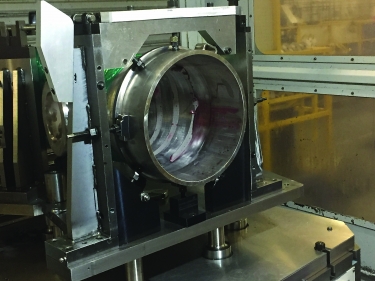
The inlet of a combustion transition piece is ready for boring in a horizontal boring mill. All images courtesy of C. Tate
In the past, as we started manufacturing parts, we struggled to machine combustion assemblies. Machining became a bottleneck process, disrupting part flow. Most of our problems resulted from boring operations.
Boring combustion baskets caused the most trouble. These long cylinders with large diameters have thin walls made from materials like Inconel, which is difficult to bore.
Our primary challenge was gaining access to the areas that needed machining. We originally used indexable boring bars with traditional steel bodies but quickly figured out they would not work because they caused chatter. We discussed several other options, including solid-carbide bars and larger-diameter specials. Eventually, we settled on mechanically dampened boring bars, which effectively eliminated chatter.
In addition, they were offered in the lengths we needed and were built to accept quick-change indexable heads. Once set in a lathe’s turret, they do not need to be removed. We simply change the head when a different-style insert is needed, which allows one bar to perform boring, grooving and threading. Flexibility reduces the overall cost of the project and shortens setup times.
Combustion transition pieces are the companion parts to combustion baskets but are considerably larger and require more machining. CTPs are not as prone to chatter because the setup is stiffer, the areas to machine are easier to reach and the walls of the part are thicker. The inlet end of a CTP resembles a large-diameter pipe. Inlet diameters are slightly different across the product line, ranging from 310mm to 320mm.
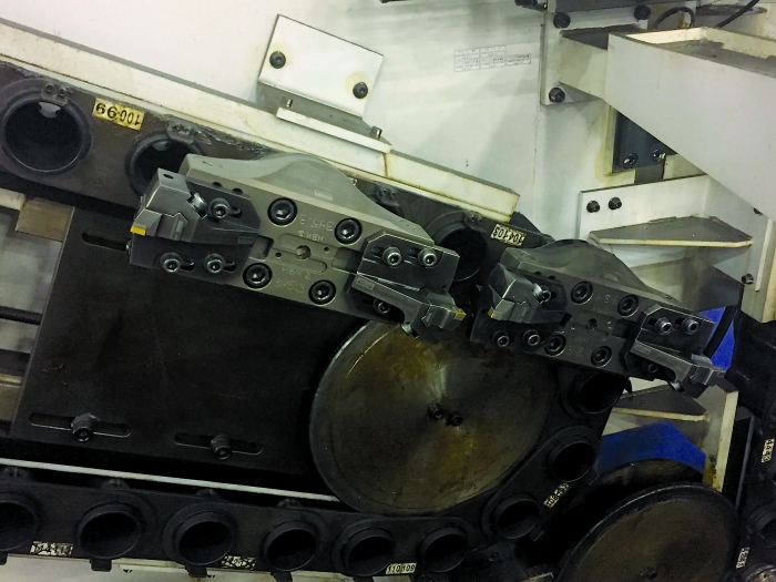
Two bridge-style boring tools in the tool chain of a horizontal boring mill. Each diameter required a dedicated tool.
Our first inlet machining operations for CTPs included helical milling. With helical milling, which was selected primarily for flexibility, we could use a single cutting tool to machine the different diameters found across the part family, thereby reducing tooling costs. Helical milling worked but was slow and plagued by premature insert failure that could break expensive milling tools. It became evident that helical milling, although effective in many other applications, was not the best choice for machining these parts.
Boring Decisions
We determined that boring would be the best option and purchased bridge-style boring tools. These tools have several advantages, starting with a Coromant Capto connection that allows us to attach various spindle adapters and extensions when needed. Bridge-style tools have a main body that will accept various subassemblies, allowing users to do ID work, OD work and face grooving. Most importantly, the costs to operate and repair the heads are far less than for the milling tools.
Modularity of these boring tools allows us to rough with simple (inexpensive) indexable holders or finish by bolting on a fine boring head that can be adjusted in 0.002mm increments. Although these bridge-style assemblies cost about $3,500 each, they are one of the best options available when boring a 320mm hole.
Each gas turbine disc has a dozen 80mm-dia. holes used to bolt the discs together into a single unit called a rotor. These holes are the most challenging boring job we have. Some of these holes are over 600mm deep; the boring tools can sag under their own weight, making accurate holes difficult to achieve.
To combat the difficulties associated with deep holes, we plan to begin using padded, or guided, tools, which are an adaptation from the automotive industry. They resemble a traditional boring head and enable a small amount of adjustment. However, they are made for a specific hole size, not a range of sizes.
Holders can be adjusted radially and axially, eliminating error from runout. Lapped guide pads placed around the circumference of the head ride on the bored hole to prevent the tool from wandering off course. We expect to see improved quality, process capability and cycle times by applying the tools.
Creating accurately sized holes can be a challenge when tolerances are tight. Add complicating factors, such as large diameters or high diameter-to-length ratios, and things can really become difficult. Learning about new technologies, understanding the available tools and learning about methods used in other industries can provide pathways to success in difficult boring operations.
Related Glossary Terms
- boring
boring
Enlarging a hole that already has been drilled or cored. Generally, it is an operation of truing the previously drilled hole with a single-point, lathe-type tool. Boring is essentially internal turning, in that usually a single-point cutting tool forms the internal shape. Some tools are available with two cutting edges to balance cutting forces.
- boring head
boring head
Single- or multiple-point precision tool used to bring an existing hole within dimensional tolerance. The head attaches to a standard toolholder and a mechanism permits fine adjustments to be made to the head within a diameter range.
- chatter
chatter
Condition of vibration involving the machine, workpiece and cutting tool. Once this condition arises, it is often self-sustaining until the problem is corrected. Chatter can be identified when lines or grooves appear at regular intervals in the workpiece. These lines or grooves are caused by the teeth of the cutter as they vibrate in and out of the workpiece and their spacing depends on the frequency of vibration.
- flat ( screw flat)
flat ( screw flat)
Flat surface machined into the shank of a cutting tool for enhanced holding of the tool.
- gang cutting ( milling)
gang cutting ( milling)
Machining with several cutters mounted on a single arbor, generally for simultaneous cutting.
- grooving
grooving
Machining grooves and shallow channels. Example: grooving ball-bearing raceways. Typically performed by tools that are capable of light cuts at high feed rates. Imparts high-quality finish.
- inner diameter ( ID)
inner diameter ( ID)
Dimension that defines the inside diameter of a cavity or hole. See OD, outer diameter.
- milling
milling
Machining operation in which metal or other material is removed by applying power to a rotating cutter. In vertical milling, the cutting tool is mounted vertically on the spindle. In horizontal milling, the cutting tool is mounted horizontally, either directly on the spindle or on an arbor. Horizontal milling is further broken down into conventional milling, where the cutter rotates opposite the direction of feed, or “up” into the workpiece; and climb milling, where the cutter rotates in the direction of feed, or “down” into the workpiece. Milling operations include plane or surface milling, endmilling, facemilling, angle milling, form milling and profiling.
- milling machine ( mill)
milling machine ( mill)
Runs endmills and arbor-mounted milling cutters. Features include a head with a spindle that drives the cutters; a column, knee and table that provide motion in the three Cartesian axes; and a base that supports the components and houses the cutting-fluid pump and reservoir. The work is mounted on the table and fed into the rotating cutter or endmill to accomplish the milling steps; vertical milling machines also feed endmills into the work by means of a spindle-mounted quill. Models range from small manual machines to big bed-type and duplex mills. All take one of three basic forms: vertical, horizontal or convertible horizontal/vertical. Vertical machines may be knee-type (the table is mounted on a knee that can be elevated) or bed-type (the table is securely supported and only moves horizontally). In general, horizontal machines are bigger and more powerful, while vertical machines are lighter but more versatile and easier to set up and operate.
- outer diameter ( OD)
outer diameter ( OD)
Dimension that defines the exterior diameter of a cylindrical or round part. See ID, inner diameter.
- threading
threading
Process of both external (e.g., thread milling) and internal (e.g., tapping, thread milling) cutting, turning and rolling of threads into particular material. Standardized specifications are available to determine the desired results of the threading process. Numerous thread-series designations are written for specific applications. Threading often is performed on a lathe. Specifications such as thread height are critical in determining the strength of the threads. The material used is taken into consideration in determining the expected results of any particular application for that threaded piece. In external threading, a calculated depth is required as well as a particular angle to the cut. To perform internal threading, the exact diameter to bore the hole is critical before threading. The threads are distinguished from one another by the amount of tolerance and/or allowance that is specified. See turning.
Author

Christopher Tate is the owner of Tate Engineering, a Natchez, Mississippi, firm that helps manufacturers solve efficiency problems. Tate, who earned master's degree in industrial technology from Mississippi State University, has 32 years of experience in the metalworking industry.