Choosing the right boring tool

Author Christopher Tate
Published
April 03, 2017 - 11:30am

Drilling, reaming and boring are the basic holemaking operations of machining. In simple terms, drilling creates a hole in a workpiece where there was no existing hole. Reaming and boring accurately enlarge holes that already exist.

Boring operations on turning machines are generally less complicated than boring operations on milling machines. With lathes, the boring tool is moved incrementally by the machine whereas with mills, the boring tool (boring head) must be adjusted to achieve the desired hole size. In theory, boring tools for turning can make any size hole as long as the bar will fit into the hole. Boring heads for milling machines, however, are limited to a specific range. 

The Basic Boring Bar

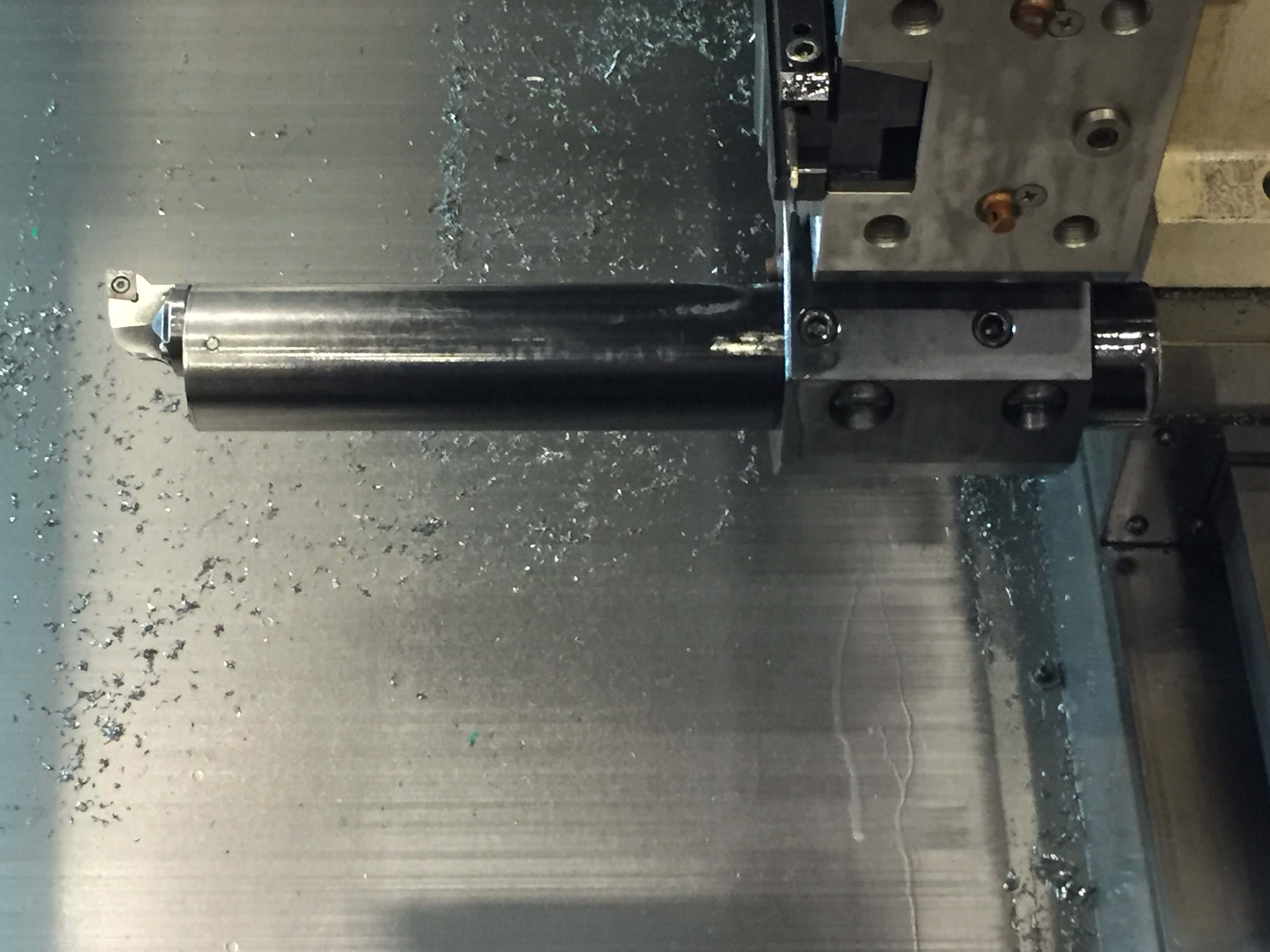
Found in every machine shop, basic boring bars that accept carbide inserts work well in most applications and are economical. 


A fine boring head used for finishing close-tolerance bores. Photo credit: Christopher Tate.
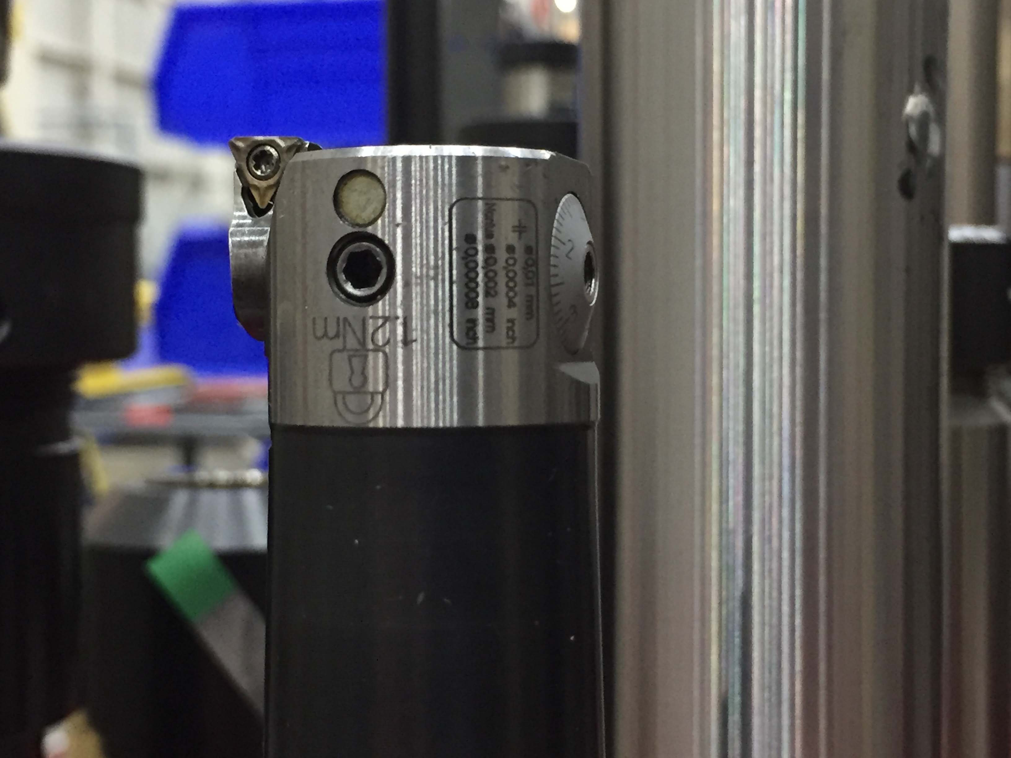
A fine boring head used for finishing close-tolerance bores. Heads like this one can be adjusted in 0.0004" increments. All images courtesy of Christopher Tate.


Unlike drills or reamers, single-edge boring bars have a single point of contact with the workpiece. As a result, the bar is unsupported, which sometimes leads to vibration, or chatter. Problems with chatter are the only significant drawback to these cutting tools.

Steel bars tend to chatter once the axial DOC exceeds 4 diameters deep. So, an end user would likely experience chatter on a 1"-dia. (25.4mm) bar if it protrudes from the turret by more than 4" (101.6mm). A machinist would say it has too much “stick-out.” 

Chatter Away

Chatter during boring operations on a lathe can be overcome. The easiest way is to apply a larger-diameter boring bar. However, a larger bar is not always an option and other means would be necessary.

Sometimes the solution is as simple as working with cutting speeds and chip loads to alter the cutting pressure on the tool. It is possible to increase tool pressure by increasing the feed rate, decreasing the cutting speed or doing both at the same time. Changing the radial DOC will also put more pressure on the tool. Sometimes users must adjust all of these variables to achieve success.

Because of their lower cost, steel boring bars are the most common, but other materials are also available. For example, cutting tool manufacturers have developed heavy-metal and carbide bars to fight chatter. Heavy-metal bars are made from tungsten alloys, which are denser than steel. These alloys work to damp vibration. Although heavy-metal bars are more expensive than steel ones, they can be applied at higher length-to-diameter ratios. Whereas steel allows a 4:1 ratio, heavy-metal bars can boost the ratio into the 6:1 or higher range with some speed-and-feed tuning.

Tungsten-carbide bars provide even higher depth-to-diameter ratios. Carbide bars are made by brazing a steel head that is machined to accept an insert onto a carbide bar. Carbide is extremely dense. It provides superior damping, allowing length-to-diameter ratios in the 8:1 or higher range. 


Vibration-damping bars have internal mechanisms that eliminate chatter. Photo credit: Christopher Tate
Vibration-damping bars have internal mechanisms that eliminate chatter. Because these bars can be expensive, buy them with interchangeable heads that accept different inserts. 


Carbide bars above 1" in diameter are not practical because of the expense. In situations where carbide would be cost-prohibitive, a tunable bar may be warranted. As the name implies, these bars have an adjustment feature that enables a user to tune the bar to a specific application. An internal mechanism alters the natural frequency of the bar, preventing chatter and allowing very large length-to-diameter ratios. Some tool manufacturers have reported the ability to make cuts at 20:1. 

Boring and Mills

Unlike the boring bar for a lathe, the tool used on a mill must be adjustable to achieve the correct size. Boring holes on a milling machine requires the use of an adjustable boring head, which adds complexity to the setup. 

The most commonly used boring heads shift the boring bar closer to or farther away from the axis of the hole to achieve the desired hole diameter. These boring heads are inexpensive. Users can bore a large range of hole sizes with these heads because the boring bar can be mounted in several different
positions. 

Boring heads are typically associated with conventional milling machines, but they can be used on CNC machines. 


This twin-head boring bar can rough large bores on a horizontal boring mill. Image courtesy of Christopher Tate.
This twin-head boring bar can rough large bores on a horizontal boring mill. 


You can engage more than one cutting edge when boring on a mill, unlike a lathe. Some boring heads are used frequently in high-production environments. Twin boring heads are set up one of two ways. In the first way, each cutting edge is set to the same diameter, allowing a fast feed rate. With the second method, the cutting edges are set on two different diameters, thereby removing more material per pass. 

Finishing Touches

Twin-style heads are best-suited for roughing because they are not easily adjusted for those times that small incremental changes to the boring diameter are necessary. When finishing, it is better to select a finish-boring head to make those small adjustments to the diameter.

Finishing tight-tolerance holes often requires special boring tools that can be accurately adjusted in small increments. These boring heads are often referred to as fine boring heads—some can be accurately adjusted in increments as small as 0.0001" (0.0025mm). Fine boring heads come in several styles. Some utilize basic round boring bars and others utilize special insert holders. They are expensive and are typically reserved for boring holes with diametric tolerances less than 0.001" (0.025mm).


This small-diameter, vibration-damping bar has several cutting heads. Image courtesy of Christopher Tate.
This small-diameter, vibration-damping bar has several cutting heads.


Boring operations and tools require machinists to pay as strict attention to details as other processes and cutting tools. Although many factors influence whether a boring operation is successful or not, adhering to the following rules will help ensure the desired results:

  • Keep the workpiece materials well supported. 
  • Minimize unsupported tool length. 
  • Use the largest-diameter tool possible. 
  • Fight chatter by adjusting tool pressure before investing in more-expensive technology.    

Related Glossary Terms

  • alloys

    alloys

    Substances having metallic properties and being composed of two or more chemical elements of which at least one is a metal.

  • boring

    boring

    Enlarging a hole that already has been drilled or cored. Generally, it is an operation of truing the previously drilled hole with a single-point, lathe-type tool. Boring is essentially internal turning, in that usually a single-point cutting tool forms the internal shape. Some tools are available with two cutting edges to balance cutting forces.

  • boring bar

    boring bar

    Essentially a cantilever beam that holds one or more cutting tools in position during a boring operation. Can be held stationary and moved axially while the workpiece revolves around it, or revolved and moved axially while the workpiece is held stationary, or a combination of these actions. Installed on milling, drilling and boring machines, as well as lathes and machining centers.

  • boring head

    boring head

    Single- or multiple-point precision tool used to bring an existing hole within dimensional tolerance. The head attaches to a standard toolholder and a mechanism permits fine adjustments to be made to the head within a diameter range.

  • chatter

    chatter

    Condition of vibration involving the machine, workpiece and cutting tool. Once this condition arises, it is often self-sustaining until the problem is corrected. Chatter can be identified when lines or grooves appear at regular intervals in the workpiece. These lines or grooves are caused by the teeth of the cutter as they vibrate in and out of the workpiece and their spacing depends on the frequency of vibration.

  • computer numerical control ( CNC)

    computer numerical control ( CNC)

    Microprocessor-based controller dedicated to a machine tool that permits the creation or modification of parts. Programmed numerical control activates the machine’s servos and spindle drives and controls the various machining operations. See DNC, direct numerical control; NC, numerical control.

  • conventional milling ( up milling)

    conventional milling ( up milling)

    Cutter rotation is opposite that of the feed at the point of contact. Chips are cut at minimal thickness at the initial engagement of the cutter’s teeth with the workpiece and increase to a maximum thickness at the end of engagement. See climb milling.

  • cutting speed

    cutting speed

    Tangential velocity on the surface of the tool or workpiece at the cutting interface. The formula for cutting speed (sfm) is tool diameter 5 0.26 5 spindle speed (rpm). The formula for feed per tooth (fpt) is table feed (ipm)/number of flutes/spindle speed (rpm). The formula for spindle speed (rpm) is cutting speed (sfm) 5 3.82/tool diameter. The formula for table feed (ipm) is feed per tooth (ftp) 5 number of tool flutes 5 spindle speed (rpm).

  • feed

    feed

    Rate of change of position of the tool as a whole, relative to the workpiece while cutting.

  • gang cutting ( milling)

    gang cutting ( milling)

    Machining with several cutters mounted on a single arbor, generally for simultaneous cutting.

  • lathe

    lathe

    Turning machine capable of sawing, milling, grinding, gear-cutting, drilling, reaming, boring, threading, facing, chamfering, grooving, knurling, spinning, parting, necking, taper-cutting, and cam- and eccentric-cutting, as well as step- and straight-turning. Comes in a variety of forms, ranging from manual to semiautomatic to fully automatic, with major types being engine lathes, turning and contouring lathes, turret lathes and numerical-control lathes. The engine lathe consists of a headstock and spindle, tailstock, bed, carriage (complete with apron) and cross slides. Features include gear- (speed) and feed-selector levers, toolpost, compound rest, lead screw and reversing lead screw, threading dial and rapid-traverse lever. Special lathe types include through-the-spindle, camshaft and crankshaft, brake drum and rotor, spinning and gun-barrel machines. Toolroom and bench lathes are used for precision work; the former for tool-and-die work and similar tasks, the latter for small workpieces (instruments, watches), normally without a power feed. Models are typically designated according to their “swing,” or the largest-diameter workpiece that can be rotated; bed length, or the distance between centers; and horsepower generated. See turning machine.

  • milling

    milling

    Machining operation in which metal or other material is removed by applying power to a rotating cutter. In vertical milling, the cutting tool is mounted vertically on the spindle. In horizontal milling, the cutting tool is mounted horizontally, either directly on the spindle or on an arbor. Horizontal milling is further broken down into conventional milling, where the cutter rotates opposite the direction of feed, or “up” into the workpiece; and climb milling, where the cutter rotates in the direction of feed, or “down” into the workpiece. Milling operations include plane or surface milling, endmilling, facemilling, angle milling, form milling and profiling.

  • milling machine ( mill)

    milling machine ( mill)

    Runs endmills and arbor-mounted milling cutters. Features include a head with a spindle that drives the cutters; a column, knee and table that provide motion in the three Cartesian axes; and a base that supports the components and houses the cutting-fluid pump and reservoir. The work is mounted on the table and fed into the rotating cutter or endmill to accomplish the milling steps; vertical milling machines also feed endmills into the work by means of a spindle-mounted quill. Models range from small manual machines to big bed-type and duplex mills. All take one of three basic forms: vertical, horizontal or convertible horizontal/vertical. Vertical machines may be knee-type (the table is mounted on a knee that can be elevated) or bed-type (the table is securely supported and only moves horizontally). In general, horizontal machines are bigger and more powerful, while vertical machines are lighter but more versatile and easier to set up and operate.

  • milling machine ( mill)2

    milling machine ( mill)

    Runs endmills and arbor-mounted milling cutters. Features include a head with a spindle that drives the cutters; a column, knee and table that provide motion in the three Cartesian axes; and a base that supports the components and houses the cutting-fluid pump and reservoir. The work is mounted on the table and fed into the rotating cutter or endmill to accomplish the milling steps; vertical milling machines also feed endmills into the work by means of a spindle-mounted quill. Models range from small manual machines to big bed-type and duplex mills. All take one of three basic forms: vertical, horizontal or convertible horizontal/vertical. Vertical machines may be knee-type (the table is mounted on a knee that can be elevated) or bed-type (the table is securely supported and only moves horizontally). In general, horizontal machines are bigger and more powerful, while vertical machines are lighter but more versatile and easier to set up and operate.

  • turning

    turning

    Workpiece is held in a chuck, mounted on a face plate or secured between centers and rotated while a cutting tool, normally a single-point tool, is fed into it along its periphery or across its end or face. Takes the form of straight turning (cutting along the periphery of the workpiece); taper turning (creating a taper); step turning (turning different-size diameters on the same work); chamfering (beveling an edge or shoulder); facing (cutting on an end); turning threads (usually external but can be internal); roughing (high-volume metal removal); and finishing (final light cuts). Performed on lathes, turning centers, chucking machines, automatic screw machines and similar machines.