Choosing a parts-marking method depends on the application
Choosing a parts-marking method depends on the application
Until a couple of years ago, the Food and Drug Administration required a unique identifier on each distinct assembly of a medical device in human- and machine-readable forms. That rule has changed. Now, every individual component in an assembly must be marked as well. Traceability is becoming more and more prevalent, not only in the medical device sector but throughout manufacturing.
Until a couple of years ago, the Food and Drug Administration required a unique identifier on each distinct assembly of a medical device in human- and machine-readable forms.
That rule has changed. Now, every individual component in an assembly must be marked as well. Traceability is becoming more and more prevalent, not only in the medical device sector but throughout manufacturing. In this emerging era of Big Data, every product and process becomes traceable—and, therefore, more easily improved by their makers. OEMs and job shops alike are investing in parts-marking capabilities.
They have a lot of options, from the newest, shiniest laser-marking systems to engraving tools and impact-based approaches such as dot-peen marking. Applications exist wherein each of these would be the best parts-marking method, and one might see multiple methods in a single facility.
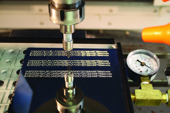
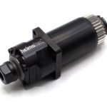
A 2L engraving tool in the company's spring-loaded engraving toolholder, which allows fast plunging into hard alloys. Image courtesy of 2L.
"We have large aerospace customers who have all the parts-marking technologies they could want—dot-peen, laser and cutting tools like ours," said Lance Nelson, president of 2L Inc., Hudson, Mass. "There are reasons for them to use each one."
Hot Technology
Aerospace is a big part of the business conducted by Beamer Laser Marking Systems, Flushing, Mich., said Brian Bittner, the company's national sales manager. "We do a lot of aerospace and medical parts, as well as [serve] lower-mix, higher-volume areas such as automotive, where the speed of laser marking is a big advantage." Laser marking cutting tools is another of the company's niches—and is a high-volume area too, he noted. Along with making, selling and servicing seven series of laser-marking systems, Beamer provides marking services on a contract basis to customers that aren't ready to purchase a system of their own.
Shining a light on an object is generally a faster process than physically cutting it with a blade or hitting it with a hammer. It would seem, therefore, that using a laser must be a faster marking method than impact marking, such as dot peen or engraving. But that isn't necessarily true.
"Don't get me wrong—impact marking is very fast as well," Bittner said. Laser has other advantages, however, including its minimal effect on the part being marked. Because the beam spot size is down to 20µm and the pulse length is so short (measured in nanoseconds), there's a negligible heat-affected zone.
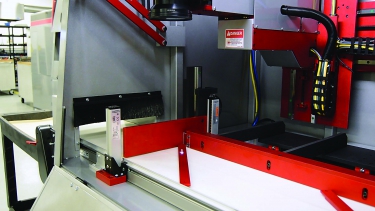
The operator can simply scan a work order or bar code to have job-specific data autopopulate in a Beamer laser-marking system. Image courtesy of Beamer Laser Marking Systems.
Moreover, laser marking common materials, such as stainless steel, is done by a process called annealing. The beam heats the metal enough to draw carbon to the surface, creating a dark spot (think of burned toast) but without melting the metal or changing its dimensions. Bittner contrasts this process with the danger of stress fractures that can be introduced from impact marking and burrs from engraving systems.
Lasers are also more versatile in terms of the marks they can make. Elaborate company logos are no more difficult to transcribe than a serial number. Moreover, with the advent of fiber lasers—which are less expensive and easier to
maintain than models based on older technology—laser marking is within the reach of more shops than ever, according to Bittner.
"There are so many applications for laser marking now that, in comparison, other methods, such as dot peen, are being seen as the old, archaic way of doing things," Bittner said. "Not that they're ever totally going away, but much of their business has dried up since laser has come around."
Making an Impact
Rick Pentz, vice president of the marking division at Dapra Corp., Bloomfield, Conn., partially agrees with that assessment. Dapra sells and services both dot-peen and laser-marking systems and offers contract marking services.
"Dot peen tends to be used less in applications where speed is a priority," he said. The process was originally developed in the 1980s, specifically "to provide a permanent way to identify jet engine components while minimizing stress the processes put on the part."
In dot-peen marking, a carbide- or diamond-tipped stylus is driven into the part to make a matrix of small but permanent indentations—dots. This process results in markings that resemble the characters created by the once ubiquitous dot-matrix printers.
The process, which was carefully managed to minimize stress in aerospace parts, caught on in other industries. A flood of inexpensive, pneumatically driven imitations were used in industries such as automotive, where speed mattered more than concerns about stress fractures, Pentz said. "It's these systems that are now being replaced by laser-marking systems."
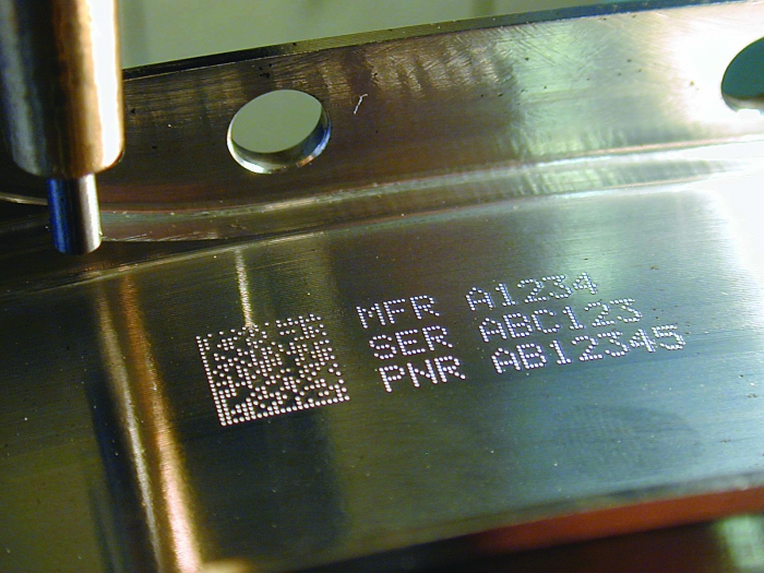
Scannable 2D dot-matrix code and tracking numbers created with a Dapra dot-peen marking system. Image courtesy of Dapra.
Dot peen is still a valued part-marking method in other industries, however. Pentz mentioned aerospace, oil and gas, and construction. In those industries, part volumes tend to be lower than in automotive. "For a 10- to 25-person machine shop, dot peen is still a very good method. It's economical, and it can do basics such as serialization and date coding that you need for traceability."
The technology has evolved over the decades. Pentz said there are still pneumatically driven systems, but for the most part the norm is now electromechanical solenoid—an all-electric system. Where the technology has changed the most, he noted, is in how data is sent to a marking system and then returned. "There's more and more focus on database connectivity and communication now—basically aiming to eliminate the need for an operator to input data. That and making the systems more compact have been the biggest movements in the technology."
Marking by Cutting
The issue of throughput—how fast a part can accurately be made—tends to drive manufacturers' decisions about which parts-marking product to buy. Laser-marking systems seem to have an advantage when it comes to speed, and dot peeners are dependable and economical.
So where does this leave companies such as 2L and other makers of engraving tools used to mark parts? According to 2L's Nelson, it leaves them doing quite well. One wonders how this can be when the engraving process is often slower than laser marking or dot peening.
The answer is not found by looking at the results of an imagined race between these different marking technologies. Instead, it's found by stepping back to consider what would have to happen before and after that race.
In the case of laser marking and most dot-peen systems, marking is done as an offline, secondary operation. The metal part must be taken out of the mill or lathe, carried to and set up in the marking system, marked and then put back into the production system. This movement and placement take time.
But when people are marking a part on a multitask machine, for example, "the engraving tool can be simply another tool in the toolchanger," Nelson pointed out. The part is already set up in the machine, so marking is just another operation with a different tool. As for programming, marking "is just another line in the program." There's no additional setup, added complexity or time lost to moving the part to an offline marking system. "That can really save time and help throughput," he said.
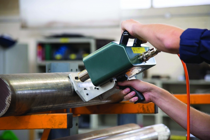
Dapra's PryorMark is a portable, hand-held, fully programmable dot-peen system. Image courtesy of Dapra.
There are many kinds of engraving tools, Nelson said, with different radii at the end, different conical-included angles and lots of different tip sizes, depending on the size of the marks to be engraved.
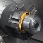
2L also makes a spring-loaded engraving toolholder. Instead of setting the engraving tool in a rigid toolholder, the engraving tool fits into the collet of a spring-loaded device, which in turn fits into the spindle. The toolholder pushes the tool into the part with the spring. "It's not rocket science—it's a fairly simple, low-cost device," Nelson said. "But it's useful because it allows faster engraving than with a rigid toolholder."
People generally plunge pretty slowly with engraving tools, being wary of the damage that can come from quickly pushing the tool—with its small, sharp point—into a hard material, such as tool steel, Nelson explained. Because the spring has give, the spring-loaded tool allows faster plunging into the part.
As multiaxis machining equipment and software have improved, 2L has had to innovate to "jog alongside them in order to keep up," Nelson said, to ensure that its tools and systems can take optimal advantage of those improvements. For example, 2L offers a CAM program that lets users enter whatever data needs to go into a 2D data matrix code, Nelson said. After typing the data, "you push a button, and the software generates the G code to create the 2D data matrix. We're trying to keep traceability and parts marking as simple as possible."