Chamfers and countersinks halt burr formation

Author Marlon Blandon
Published
October 10, 2017 - 04:00pm

The purpose of chamfering or countersinking an internal threaded hole is typically to avoid creating a raised burr that can prevent a mating part from properly seating with another flat surface. In addition, when the mating part is placed on a burr, the burr can be forced down, effectively deforming the internal thread and increasing the potential for cross threading.

A chamfer or countersink may also be specified on a part drawing to help a bolt properly align or start. And adding a chamfer or countersink to a hole that will be tapped will always aid when starting the tap.

For reasons such as these, the vast majority of threaded holes require some type of chamfer or countersink. As a result, this is one of the most common machining operations. And it’s one that can usually be improved.


Threaded-hole chamfers normally have included angles of 120° or 90°, with 90° being most common. Image courtesy of Emuge.
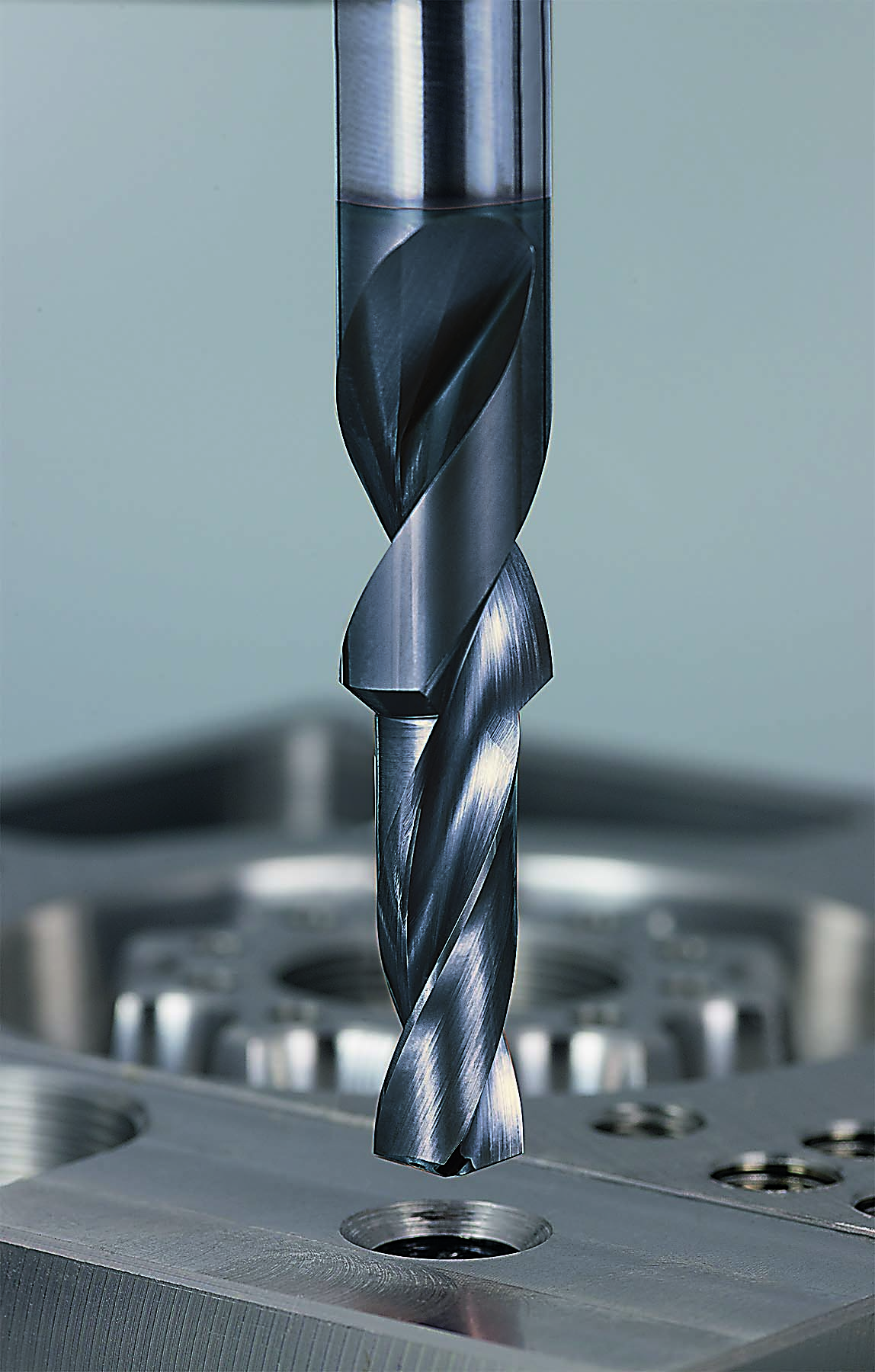
All images courtesy of Emuge.


Threaded-hole chamfers normally have included angles of 120° or 90°, with 90° being most common. The OD and depth of the chamfer sometimes are specified on the blueprint. However, it is frequently left to the discretion of the machinist or programmer to determine the depth or OD of the chamfered hole.

While a DIN standard does not exist, there are a few well-worn machinist rules of thumb. The most common practice is to apply a chamfer diameter that is 0.010" to 0.015" (0.254mm to 0.381mm) larger than the thread’s major diameter. This will eliminate the burr and provide enough depth to act as a starter for a mating bolt.

Machining Methods

Creating a chamfer or countersink can be accomplished in various ways, some of which are more efficient than others. Formerly, the customary way of machining a chamfer on a hole to be threaded was to apply a 120° or 90° countersinking tool after the initial drilling operation.

Today, many machine shops apply an NC spot drill with a 90° point angle to accomplish spot drilling, countersinking and chamfering, which saves tool-change time and reduces tooling costs. The NC spot drill is used as a lead tool prior to drilling to create the 90° included angle. While this may be convenient, don’t do it if you are holemaking with newer, high-penetration-rate carbide drills. These drills are manufactured with a 140° point angle. Applying a 90° spot drill prior to drilling with a 140° carbide drill will lead to chipped corners on the latter drill and premature tool failure. The tool sequence must be changed if a carbide drill is applied for making a hole that’s to be tapped.

The proper tool sequence becomes: drill, chamfer (or countersink) and tap. In this scenario, a countersink tool or a chamfer mill with a 120° or 90° point angle is the best choice. By selecting the proper tool sequence, the tool life of the carbide drill will increase dramatically.


Countersinks and chamfers are called out in various ways on blueprints or can be left to the machinist’s discretion. Image courtesy of Emuge.  Countersinks and chamfers are called out in various ways on blueprints or can be left to the machinist’s discretion. Image courtesy of Emuge.    Countersinks and chamfers are called out in various ways on blueprints or can be left to the machinist’s discretion. Image courtesy of Emuge.
Countersinks and chamfers are called out in various ways on blueprints or can be left to the machinist’s discretion.


In addition, care should be taken when aligning a tool to countersink or chamfer a hole. Misalignment can be detrimental to part quality and function. A chamfer mill can cut a circular chamfer via circular interpolation but may not be the best design for straight plunging. Conversely, traditional HSS countersinks are designed for plunging applications, but they are not designed for following a helical circular interpolation toolpath.

Combining Operations

The most efficient, quickest way to produce a chamfer in a hole that’s to be threaded is with a step drill that combines drilling and countersinking. By having a 90° countersink step angle in the drill, the hole and chamfer are produced in one operation. 

Combining two machining operations into one reduces tool-change time, cycle time and tool inventory. Another benefit is that when a step drill produces the chamfer, the location of the chamfer is completely concentric with the hole.

If a step drill is selected as the preferred method of hole preparation, be wary of using modified standard drills in which the pilot’s minor diameter is ground onto an existing single-diameter drill. The web thickness of the minor diameter will likely be too thick, and chip flow will be impeded. The minor diameter is commonly applied without a margin for clearance purposes, which also lessens the performance of the drill by creating friction on the OD.

Step drills, especially carbide ones, should be ground from a carbide rod and not by modifying an existing finished tool so the web and margin fit the application. Standard step drills are available, and some tool manufacturers quickly deliver them to allow an end user to vary the tapped hole depth in blind-hole applications.

Process improvement is always a goal for progressive manufacturers. Although chamfers and countersinks are common features for holes that will be threaded, the machining sequence is not a standardized process and is—as is the case with most processes—open to improvement.

Related Glossary Terms

  • blind-hole

    blind-hole

    Hole or cavity cut in a solid shape that does not connect with other holes or exit through the workpiece.

  • burr

    burr

    Stringy portions of material formed on workpiece edges during machining. Often sharp. Can be removed with hand files, abrasive wheels or belts, wire wheels, abrasive-fiber brushes, waterjet equipment or other methods.

  • chamfering

    chamfering

    Machining a bevel on a workpiece or tool; improves a tool’s entrance into the cut.

  • clearance

    clearance

    Space provided behind a tool’s land or relief to prevent rubbing and subsequent premature deterioration of the tool. See land; relief.

  • countersink

    countersink

    Tool that cuts a sloped depression at the top of a hole to permit a screw head or other object to rest flush with the surface of the workpiece.

  • countersinking

    countersinking

    Cutting a beveled edge at the entrance of a hole so a screw head sits flush with the workpiece surface.

  • flat ( screw flat)

    flat ( screw flat)

    Flat surface machined into the shank of a cutting tool for enhanced holding of the tool.

  • high-speed steels ( HSS)

    high-speed steels ( HSS)

    Available in two major types: tungsten high-speed steels (designated by letter T having tungsten as the principal alloying element) and molybdenum high-speed steels (designated by letter M having molybdenum as the principal alloying element). The type T high-speed steels containing cobalt have higher wear resistance and greater red (hot) hardness, withstanding cutting temperature up to 1,100º F (590º C). The type T steels are used to fabricate metalcutting tools (milling cutters, drills, reamers and taps), woodworking tools, various types of punches and dies, ball and roller bearings. The type M steels are used for cutting tools and various types of dies.

  • included angle

    included angle

    Measurement of the total angle within the interior of a workpiece or the angle between any two intersecting lines or surfaces.

  • interpolation

    interpolation

    Process of generating a sufficient number of positioning commands for the servomotors driving the machine tool so the path of the tool closely approximates the ideal path. See CNC, computer numerical control; NC, numerical control.

  • milling machine ( mill)

    milling machine ( mill)

    Runs endmills and arbor-mounted milling cutters. Features include a head with a spindle that drives the cutters; a column, knee and table that provide motion in the three Cartesian axes; and a base that supports the components and houses the cutting-fluid pump and reservoir. The work is mounted on the table and fed into the rotating cutter or endmill to accomplish the milling steps; vertical milling machines also feed endmills into the work by means of a spindle-mounted quill. Models range from small manual machines to big bed-type and duplex mills. All take one of three basic forms: vertical, horizontal or convertible horizontal/vertical. Vertical machines may be knee-type (the table is mounted on a knee that can be elevated) or bed-type (the table is securely supported and only moves horizontally). In general, horizontal machines are bigger and more powerful, while vertical machines are lighter but more versatile and easier to set up and operate.

  • numerical control ( NC)

    numerical control ( NC)

    Any controlled equipment that allows an operator to program its movement by entering a series of coded numbers and symbols. See CNC, computer numerical control; DNC, direct numerical control.

  • outer diameter ( OD)

    outer diameter ( OD)

    Dimension that defines the exterior diameter of a cylindrical or round part. See ID, inner diameter.

  • point angle

    point angle

    Included angle at the point of a twist drill or similar tool; for general-purpose tools, the point angle is typically 118°.

  • tap

    tap

    Cylindrical tool that cuts internal threads and has flutes to remove chips and carry tapping fluid to the point of cut. Normally used on a drill press or tapping machine but also may be operated manually. See tapping.

  • threading

    threading

    Process of both external (e.g., thread milling) and internal (e.g., tapping, thread milling) cutting, turning and rolling of threads into particular material. Standardized specifications are available to determine the desired results of the threading process. Numerous thread-series designations are written for specific applications. Threading often is performed on a lathe. Specifications such as thread height are critical in determining the strength of the threads. The material used is taken into consideration in determining the expected results of any particular application for that threaded piece. In external threading, a calculated depth is required as well as a particular angle to the cut. To perform internal threading, the exact diameter to bore the hole is critical before threading. The threads are distinguished from one another by the amount of tolerance and/or allowance that is specified. See turning.

  • toolpath( cutter path)

    toolpath( cutter path)

    2-D or 3-D path generated by program code or a CAM system and followed by tool when machining a part.

  • web

    web

    On a rotating tool, the portion of the tool body that joins the lands. Web is thicker at the shank end, relative to the point end, providing maximum torsional strength.

Author

Emuge Corp.

Marlon Blandon is thread mills product manager for Emuge Corp., West Boylston, Mass. For more information about the company’s cutting tools, call (800) 323-3013 or visit www.emuge.com.