Cartridges to hold indexable inserts in cutting tools have been used for many years. In modern manufacturing environments, cartridges have a permanent place in tools for boring, turning, milling and drilling. Cartridges became popular on shop floors for many reasons:
- Cartridges allow tool adjustability when a more accurate insert location is required. As a separate component, a cartridge can be accurately moved independently from other cutting elements of the tool to compensate for imperfections in the manufacturing process.
- Cartridges protect expensive cutter bodies. Collisions are a typical failure mode in a cutting operation. Even with the improved verification environment of modern CAD/CAM systems, as well as employing tool monitoring systems, there is a high chance of a collision between the cutting part of the tool and the workpiece. Positioning of cartridges is done so that they take all “abuse” and protect the body from severe damage.
- Cartridges reduce tooling costs by using standard components produced by multiple vendors on the open market.
- Cartridges improve the quality of cutting tools by using premium alloy steels with appropriate heat treatment to allow softer and lightweight materials for tool bodies.
- Cartridges enable users to build multiple stations on a tool to combine many different operations in a single path. This capability plays an important role in increasing the material removal rate, especially in mass production.
The main standard describing types and sizes of cartridges, ISO 5611 (cartridges, type A, for indexable inserts — dimensions), had a major update in 2015 and now consists of 12 substandards, from ISO 5611-1:2015 to ISO 5611-12:2015. Historically, this evolved from German standard DIN 4985.
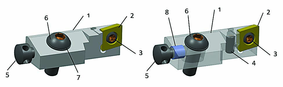
The typical design of an ISO 5611 cartridge (see Figure 1) includes 1) a solid body made from heat-treated alloy steel; 2) a cutting insert fabricated from carbide, ceramic or superhard cutting materials like PCD or CBN; 3) an insert retaining screw; 4) a radial adjustment screw; 5) an axial adjustment screw; 6) a cartridge clamping screw; 7) a washer; and 8) an optional thread retaining element, or helicoil.
The standard itself does not dictate cartridge design but only the main dimensions. Over time, however, different manufacturers unified to create a principal design, and this is why all cartridges look alike today.
Over the past three decades, manufacturers have significantly improved the design and performance of machine tools. Spindles have become faster and more rigid. Accuracy has become higher. Communications and data acquisition systems have increased machine efficiency and output. Many breakthroughs similarly were made in the development of new carbide grades and superhard cutting materials. But cutting tool designs — particularly with ISO cartridges — are lagging behind this progress in the rest of the industry.
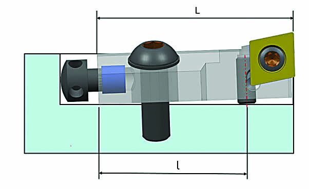
Several factors are especially outdated (see Figure 2) and take away from machine tool achievements:
- Using standard socket setscrews with a large pitch of thread creates adjustment resolution that is below that of modern demands. For example, for the cartridge 10CA (10 = distance to the cutting edge in millimeters; C for cartridge; A for type A), the diameter of the screw thread is M4 mm, and the pitch is equal to 0.7 mm. This means that to complete one revolution of the screw, the cartridge will move radially 0.7 mm.
- The ratio of L/l>>1 reduces the resolution of adjustment even further.
- Due to the rigid body of the cartridge, adjustment is possible only by stretching clamping screw 6. (See Figure 1.) Practically, smaller screw 4 is working against larger screw 6. (See Figure 1.)
- There is no firm body support under the application of the cutting force because of clearance between the cartridge body and pocket floor.
These drawbacks lead to a cumbersome adjustment process that requires multiple repetitions. To make an adjustment, an operator usually applies reduced torque to clamping screw 6. (See Figure 1.) Then, he or she actuates adjustment screw 4 and secures clamping screw 6 to the necessary specification. During this process, the cartridge body slightly deforms and the target position of the insert changes. From this point on, everything depends on operator experience. Some operators start over again by releasing the clamping screw while others use a radial screw to fine-tune the position of the cutting edge. It’s impossible to predict how hard the radial adjustment screw will be jammed by the clamping screw. The size of the hex or Torx tool driving the screw is small and may be insufficient to overcome the friction.
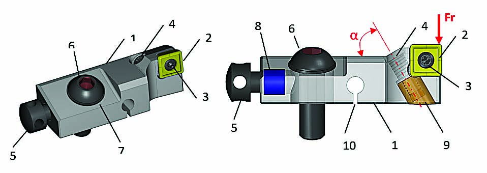
To address the shortcomings of the traditional design, Sandvik Coromant Co. developed a cartridge concept (see Figure 3) that realigned a new cartridge with advances achieved in machine tools.
This new cartridge is built on the flexible body 1 platform as shown in Figure 3. Insert 2 is secured by screw 3 in the front part of the cartridge. Clamping screw 6 with washer 7 and thread retainer 8 are similar to the original design. The game changer is the incorporated differential screw 4 pared with push pad 9. Both threads on the differential screw are made of the same lead but different pitch. For example, one thread can be M4 mm and the other M4.25 mm. This makes the resulting pitch 0.25 mm, which is much smaller than a traditional design (0.7 mm).
In addition, radial adjustment screw 4 is positioned on an angle α = 60 degrees to refine the resolution of adjustment even more. The actual resolution of adjustment in 10CA cartridges is 0.019 mm (0.0007") per 90 degrees of rotation of the adjustment screw. In practical application, an operator can dependably adjust the position of the cutting edge with an accuracy of up to 0.001 mm (0.00004").
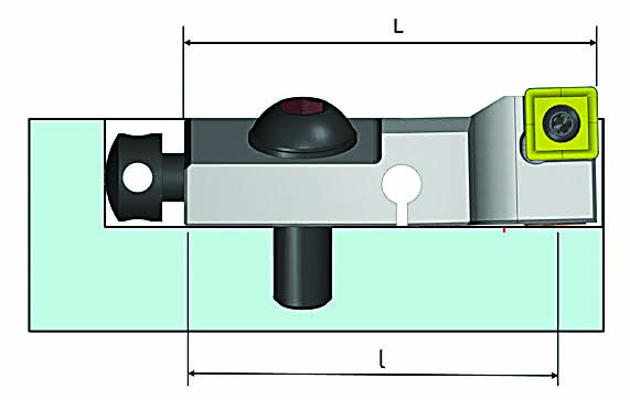
Another benefit of the push pad is strong support in the area where the radial vector of the cutting force (Fr) has the highest impact and reduced ratio L/l. (See Figure 4.)
A quintessential feature of this design is the flexible body of the cartridge, which is created by recess 10. (See Figure 3.) It requires and allows constant pre-loading between cartridges and the host cutting tool. One positive effect of this is zero backlash in the differential couple and, as a result, smooth adjustment in both directions: up and down. There is also no need to release the cartridge clamping screw when performing an adjustment. This dramatically reduces maintenance time and makes the tool much more user-friendly.
When nominal pre-load in the cartridge body was calculated, Sandvik Coromant took into consideration the following factors:
- Additional maximum deformation of 0.2 mm (0.008") for compensation of the cutting edge wear.
- The effect of centrifugal force for high-speed applications — for example, machining of aluminum with PCD inserts.
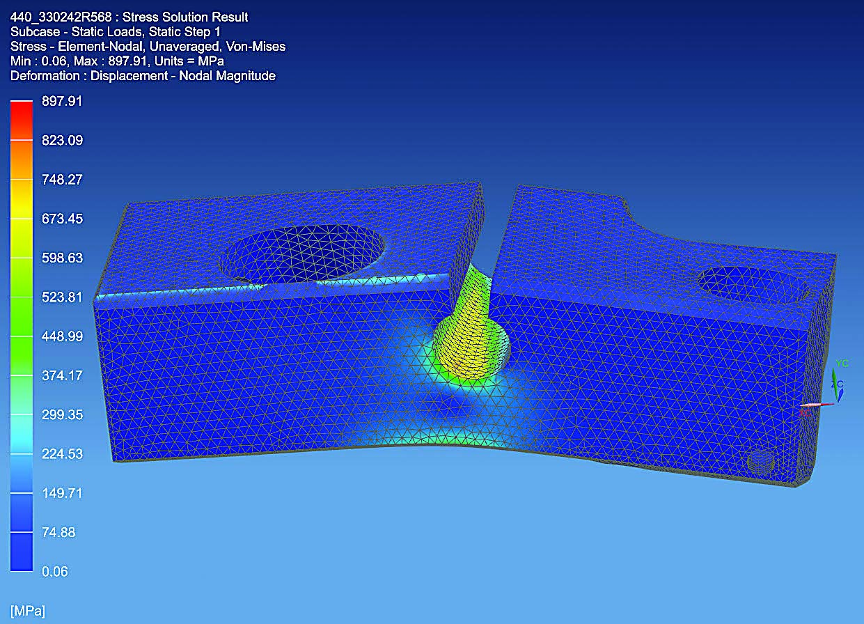
- Maximum stress in the critical cross section of the body. (See Figure 5.)
Maximum additional deformation of the cartridge front part is necessary to compensate for dimensional wear of the cutting edge for the duration of the complete operation. The intent of the design was to stay within the linear range of deformation and prevent fatigue failure. After the worn insert is indexed and the cartridge is adjusted to nominal dimension, stress is automatically reduced to the nominal.
In the case of high-speed machining, the front part of the cartridge harnesses centrifugal force in accordance with equation (1):
Fc = 0.01097 m r nrpm2 (1)
Where
m = mass in kg
r = radius of center mass in m
nrpm = revolutions per minute
A typical boring tool for machining multiple surfaces is shown in Figure 6. Front inserts are performing a roughing operation while others are finishing and chamfering.
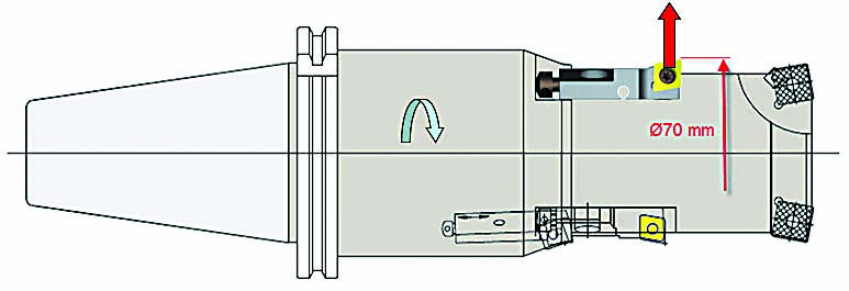
The fact that the speed of the rotation nrpm is presented in a power of two tells the importance of considering the effect of centrifugal force on the nominal pre-load of the cartridge. On one side, centrifugal force is reducing the pre-load by trying to “lift” the front part of the cartridge from the hosting body. On another side, centrifugal force increases stress in the critical section. For example, if this tool is rotating at nrpm = 8,000 rpm and the mass of the front part is m = 0.0199 kg at 0 rpm, then centrifugal force will reach 489 N (110 lbs.).
Based on deep engineering analysis, Sandvik Coromant established geometrical constraints for the new cartridge while still honoring the requirements of the standard ISO 5611. The new design is fully interchangeable with original cartridges and has been proven in the field.
Sandvik Coromant’s application analysis suggests that 75% of finish operations can be achieved with cartridges of size 10CA, which have a length L = 50 mm, height F = 14 mm and distance to the cutting edge H = 10 mm. The company also identified three main types of common cartridges that can satisfy the majority of applications. Other types and sizes of ISO 5611 cartridges are available as well.
Sandvik Coromant recommends using a spacer heat-treated to 60 HRC whenever possible. This significantly increases tool life of the tooling body by preventing any plastic deformations in the area of contact between the pocket floor and push pad 9. (See Figure 3.)
Another benefit of the spacer is the ability to grind its thickness to adapt the cartridge to the different boring diameter, as well as the ability to use lighter and softer materials like aluminum, magnesium and carbon fiber for the tooling body. The spacer absorbs high pressure during the cutting process and provides protection for the cutter body. To allow free flow of coolant, the spacer has a relief.
The main benefits of the new, patented fine adjustment cartridge design can be summed up as follows: Cartridges meet the requirements of standard ISO 5611; there is a high resolution of adjustment of 0.001 mm; backlash is absent in the adjustment system; there is no need to unclamp the cartridge during adjustment; a sufficient range of 0.2 mm compensates for wear of the cutting edge; and there is high stability of the cartridge with support under the cutting edge.
This new design elevates the product to the technological level of modern machine tools. Utilizing new cartridges for existing operations can more than double tool life and significantly improve the experience for end users.
Contact Details
Related Glossary Terms
- alloy steels
alloy steels
Steel containing specified quantities of alloying elements (other than carbon and the commonly accepted amounts of manganese, sulfur and phosphorus) added to cause changes in the metal’s mechanical and/or physical properties. Principal alloying elements are nickel, chromium, molybdenum and silicon. Some grades of alloy steels contain one or more of these elements: vanadium, boron, lead and copper.
- backlash
backlash
Reaction in dynamic motion systems where potential energy that was created while the object was in motion is released when the object stops. Release of this potential energy or inertia causes the device to quickly snap backward relative to the last direction of motion. Backlash can cause a system’s final resting position to be different from what was intended and from where the control system intended to stop the device.
- boring
boring
Enlarging a hole that already has been drilled or cored. Generally, it is an operation of truing the previously drilled hole with a single-point, lathe-type tool. Boring is essentially internal turning, in that usually a single-point cutting tool forms the internal shape. Some tools are available with two cutting edges to balance cutting forces.
- chamfering
chamfering
Machining a bevel on a workpiece or tool; improves a tool’s entrance into the cut.
- clearance
clearance
Space provided behind a tool’s land or relief to prevent rubbing and subsequent premature deterioration of the tool. See land; relief.
- coolant
coolant
Fluid that reduces temperature buildup at the tool/workpiece interface during machining. Normally takes the form of a liquid such as soluble or chemical mixtures (semisynthetic, synthetic) but can be pressurized air or other gas. Because of water’s ability to absorb great quantities of heat, it is widely used as a coolant and vehicle for various cutting compounds, with the water-to-compound ratio varying with the machining task. See cutting fluid; semisynthetic cutting fluid; soluble-oil cutting fluid; synthetic cutting fluid.
- cutting force
cutting force
Engagement of a tool’s cutting edge with a workpiece generates a cutting force. Such a cutting force combines tangential, feed and radial forces, which can be measured by a dynamometer. Of the three cutting force components, tangential force is the greatest. Tangential force generates torque and accounts for more than 95 percent of the machining power. See dynamometer.
- fatigue
fatigue
Phenomenon leading to fracture under repeated or fluctuating stresses having a maximum value less than the tensile strength of the material. Fatigue fractures are progressive, beginning as minute cracks that grow under the action of the fluctuating stress.
- gang cutting ( milling)
gang cutting ( milling)
Machining with several cutters mounted on a single arbor, generally for simultaneous cutting.
- milling
milling
Machining operation in which metal or other material is removed by applying power to a rotating cutter. In vertical milling, the cutting tool is mounted vertically on the spindle. In horizontal milling, the cutting tool is mounted horizontally, either directly on the spindle or on an arbor. Horizontal milling is further broken down into conventional milling, where the cutter rotates opposite the direction of feed, or “up” into the workpiece; and climb milling, where the cutter rotates in the direction of feed, or “down” into the workpiece. Milling operations include plane or surface milling, endmilling, facemilling, angle milling, form milling and profiling.
- pitch
pitch
1. On a saw blade, the number of teeth per inch. 2. In threading, the number of threads per inch.
- polycrystalline diamond ( PCD)
polycrystalline diamond ( PCD)
Cutting tool material consisting of natural or synthetic diamond crystals bonded together under high pressure at elevated temperatures. PCD is available as a tip brazed to a carbide insert carrier. Used for machining nonferrous alloys and nonmetallic materials at high cutting speeds.
- relief
relief
Space provided behind the cutting edges to prevent rubbing. Sometimes called primary relief. Secondary relief provides additional space behind primary relief. Relief on end teeth is axial relief; relief on side teeth is peripheral relief.
- turning
turning
Workpiece is held in a chuck, mounted on a face plate or secured between centers and rotated while a cutting tool, normally a single-point tool, is fed into it along its periphery or across its end or face. Takes the form of straight turning (cutting along the periphery of the workpiece); taper turning (creating a taper); step turning (turning different-size diameters on the same work); chamfering (beveling an edge or shoulder); facing (cutting on an end); turning threads (usually external but can be internal); roughing (high-volume metal removal); and finishing (final light cuts). Performed on lathes, turning centers, chucking machines, automatic screw machines and similar machines.
About the authors
Eugene Kocherovsky is product development engineer for the automotive engine group and Curt Holbrook is manager of automotive engineering projects at Sandvik Coromant Co. in Mebane, North Carolina. For more information, call 800-726-3845 or visit www.sandvik.coromant.com.
