You may have heard of ultraprecision machining (UPM), also known as diamond turning. Its primary application is machining optical-grade surfaces for injection molds, which are used to make contact lenses, LEDs for TVs and head-up displays in fighter aircraft and luxury cars.
UPM can produce complex shapes with submicron tolerances and surface finishes best measured in nanometers, provided the machine is given a commensurately accurate toolpath. That’s where Aachen, Germany-based ModuleWorks GmbH comes in.
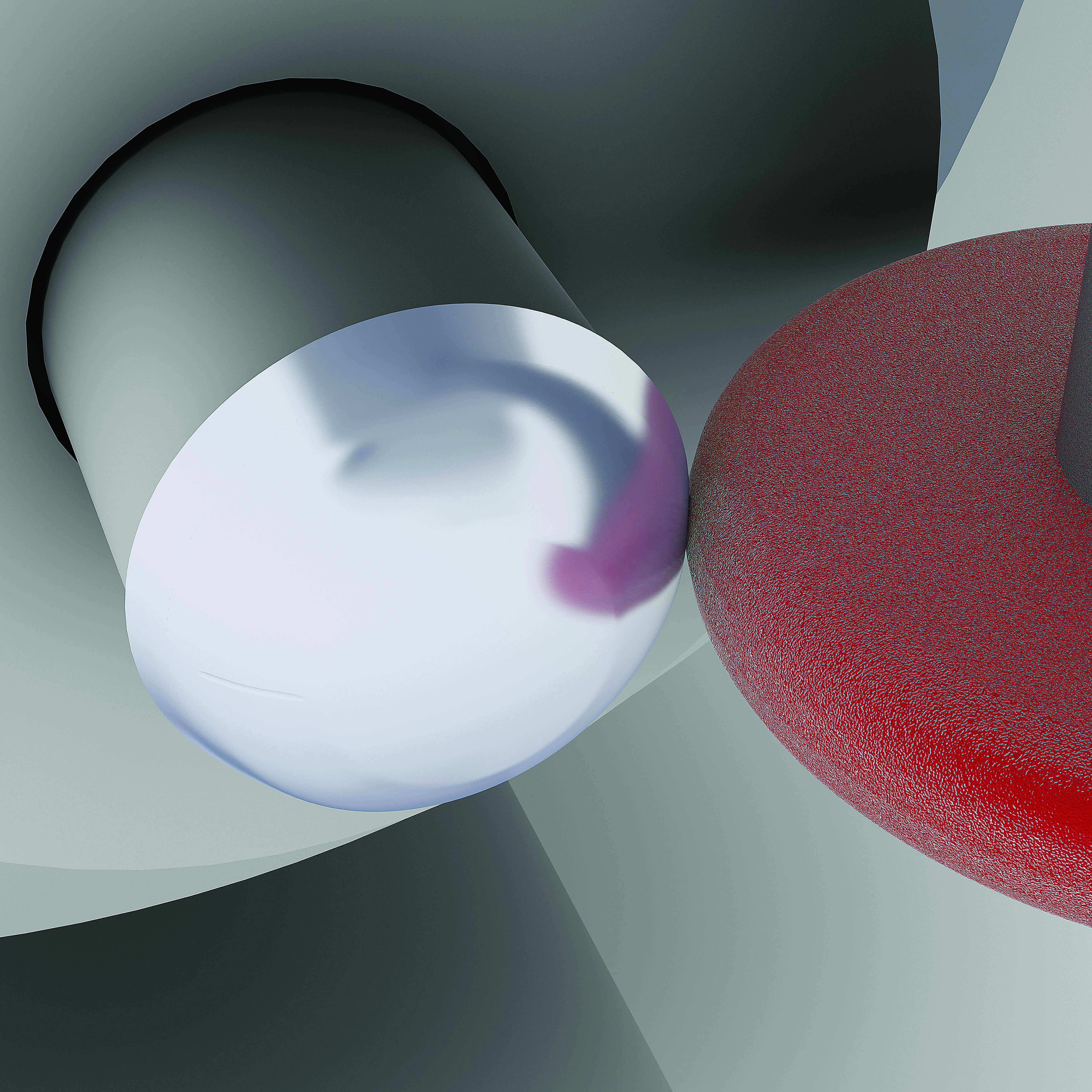
Simulation of a grinding process on a UPM machine. Image courtesy of ModuleWorks.
ModuleWorks team members recently worked on a research project with optics and metrology equipment manufacturer Zeiss International, based in Oberkochen, Germany. The team members were tasked with developing CAD/CAM software that’s optimized for UPM. Features include spiral toolpath and zigzag calculations for 2D and 3D optics, advanced nonuniform rational basis spline (NURBS) capabilities, multiple-surface and lens support, and the generation of toolpaths needed to support the “fast tool” and “slow slide servo” technologies employed on these machines.
It wasn’t enough to create complex, ultraprecision toolpath data and hope that the UPM machine would produce the desired shape. Zeiss engineers asked for adaptive-software technology that could read and analyze point clouds obtained by measuring machined surfaces and then have the CAM system adjust the toolpaths accordingly.
“You might have metrology data coming from an interferometer, for example, and want to adapt the programmed geometry to compensate for any machine- or process-related deviation,” said Lothar Glasmacher, ModuleWorks project director. As for the toolpaths themselves, Glasmacher explained that conventional CAD/CAM systems do not support the cutting patterns needed for UPM, nor are the algorithms accurate enough to meet the geometric requirements of a smartphone camera lens or the optics for an advanced telescope mirror, for example. “This new technology can calculate dimensional values out to the 12th decimal place.”
As a result of its work with Zeiss, ModuleWorks offers an “optics component” module for 3D programming of UPM turning, milling and grinding machines. It uses a multiple-threading, 64-bit algorithm for rapid calculation of multimillion toolpath points and supports simulation of multiple spindles and turrets, according to the company. In addition, it can be combined with conventional CAD/CAM software for use with 3-, 4- and 5-axis machine tools.
Related Glossary Terms
- computer-aided manufacturing ( CAM)
computer-aided manufacturing ( CAM)
Use of computers to control machining and manufacturing processes.
- gang cutting ( milling)
gang cutting ( milling)
Machining with several cutters mounted on a single arbor, generally for simultaneous cutting.
- grinding
grinding
Machining operation in which material is removed from the workpiece by a powered abrasive wheel, stone, belt, paste, sheet, compound, slurry, etc. Takes various forms: surface grinding (creates flat and/or squared surfaces); cylindrical grinding (for external cylindrical and tapered shapes, fillets, undercuts, etc.); centerless grinding; chamfering; thread and form grinding; tool and cutter grinding; offhand grinding; lapping and polishing (grinding with extremely fine grits to create ultrasmooth surfaces); honing; and disc grinding.
- metrology
metrology
Science of measurement; the principles on which precision machining, quality control and inspection are based. See precision machining, measurement.
- milling
milling
Machining operation in which metal or other material is removed by applying power to a rotating cutter. In vertical milling, the cutting tool is mounted vertically on the spindle. In horizontal milling, the cutting tool is mounted horizontally, either directly on the spindle or on an arbor. Horizontal milling is further broken down into conventional milling, where the cutter rotates opposite the direction of feed, or “up” into the workpiece; and climb milling, where the cutter rotates in the direction of feed, or “down” into the workpiece. Milling operations include plane or surface milling, endmilling, facemilling, angle milling, form milling and profiling.
- toolpath( cutter path)
toolpath( cutter path)
2-D or 3-D path generated by program code or a CAM system and followed by tool when machining a part.
- turning
turning
Workpiece is held in a chuck, mounted on a face plate or secured between centers and rotated while a cutting tool, normally a single-point tool, is fed into it along its periphery or across its end or face. Takes the form of straight turning (cutting along the periphery of the workpiece); taper turning (creating a taper); step turning (turning different-size diameters on the same work); chamfering (beveling an edge or shoulder); facing (cutting on an end); turning threads (usually external but can be internal); roughing (high-volume metal removal); and finishing (final light cuts). Performed on lathes, turning centers, chucking machines, automatic screw machines and similar machines.
Author

Kip Hanson is a contributing editor for Cutting Tool Engineering magazine. Contact him by phone at (520) 548-7328 or via e-mail at [email protected].