This article is about boring holes with a milling machine. I make a huge variety of parts in quantities of one or two. This is not about large-quantity manufacturing. That’s a different world from where I live. Here, I’ll discuss how to make a bore to accept an SKF 6207 ball bearing unit that has an outer diameter of 72 mm.
I use a 2" Criterion boring head that is direct-mounted to a toolholder with a 7/8-20 thread. This boring head has an indexed dial screw with 0.001" gradations for setting the boring diameter, so I’m using inch dimensions in this column. Besides, my customer gave a print of the part to me that specifies the bore as 2.8351"/2.8344".
There is some machinist’s skill involved with the boring that can make the process easy and reliable. I find this kind of job fun to do. Accuracy has value, and it can be rewarding in money and satisfaction. Also, this customer has been coming back for 35 years, and I like that scene.
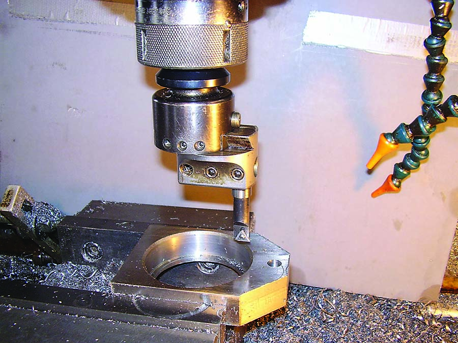
Figure 1 shows the part and the boring tool on the milling machine. Before boring, I make the hole 0.1" undersize with a 0.5" roughing endmill, then 0.06" undersize with a finishing endmill. This part has a land in the hole for the bearing to seat against. The depth and inner diameter of that feature are set with the endmills. Then the boring operation takes place.
Note the indexable tool. Carbide holds edges longer than high-speed steel tools, and for fussy dimensions it saves trouble. If an edge goes dull partway through the process, it can result in an oversize bore and a piece of scrap.
There are 5.5" between the point of the tool and the spindle nose. There is going to be deflection in the cutter setup when making a cut. The faster the metal removal, the more deflection there is. And remember that deflection makes chatter, and then the surface finish will be bad.
This bore has a tolerance of 0.0005" with a surface finish better than 63 micro-inches, so care must be taken to hit both marks. The insert has a 0.015" nose radius, and I cut the relief angle on the back of the cutting edge to 30 degrees.
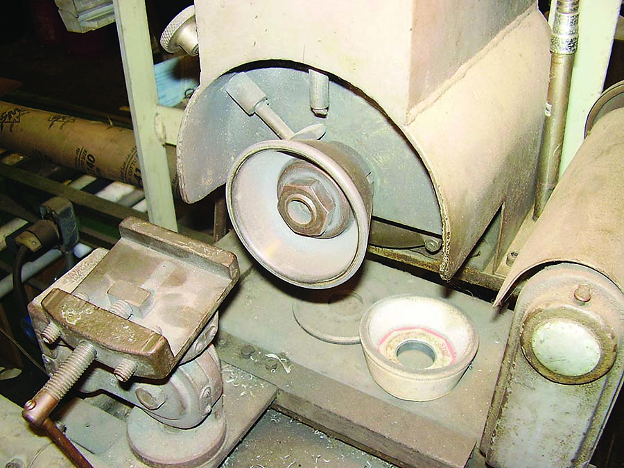
Figure 2 shows the cutter grinder that I use to modify inserts. It uses a cup-shaped diamond wheel. Carbide does wear, and when taking a light cut dullness on the cutting edge makes the tool skate on the surface of the workpiece and creates inconsistent results.
I use a boring cycle on the milling machine: Feed in, dwell at the bottom of the cut, and then feed out. If the tool is cutting while retracting or the finish is inconsistent, then it could stand sharpening.
I have found that taking off 0.015" on the diameter at a feed rate of 1.2 ipm and 200 rpm until the bore is 0.015" under provides consistent results. With smaller bores, I still use the 200 rpm speed because it’s that 5.5" overhang that causes the chatter and not so much the diameter of the bore.
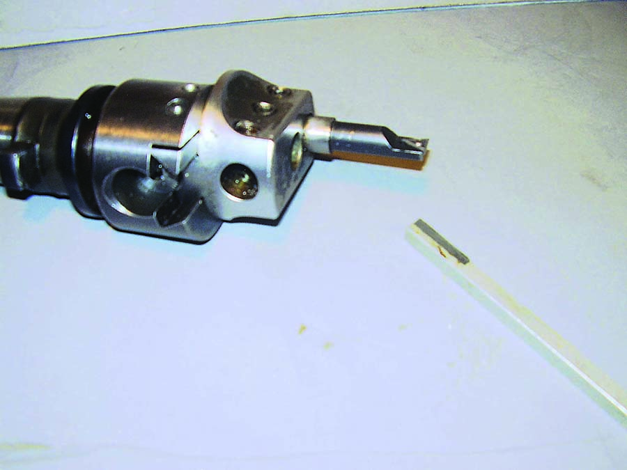
When I reach 0.15", I dress the edge. Figure 3 shows the boring tool with a diamond file. I put on my magnifying eyes and use the file to get a nice, sharp edge. It just takes a touch on the outside of the insert, but, man, it works. Then I run the tool again without coolant and check the measurement and finish.
Cooling of the tool or workpiece is not needed with this light cut, and I like to see how the work is progressing. Is the finish nice and consistent? (Fun is where you find it.) Then cut to 0.005" under and check to see if the tool took out the dialed-in cut. Cut to 0.002" under, measure again, and then hit the marks.
This might seem like a lot of time to make one bore, but if it comes out big or rough, then I will need to start the whole job again. Well, you get the picture.
Related Glossary Terms
- boring
boring
Enlarging a hole that already has been drilled or cored. Generally, it is an operation of truing the previously drilled hole with a single-point, lathe-type tool. Boring is essentially internal turning, in that usually a single-point cutting tool forms the internal shape. Some tools are available with two cutting edges to balance cutting forces.
- boring head
boring head
Single- or multiple-point precision tool used to bring an existing hole within dimensional tolerance. The head attaches to a standard toolholder and a mechanism permits fine adjustments to be made to the head within a diameter range.
- chatter
chatter
Condition of vibration involving the machine, workpiece and cutting tool. Once this condition arises, it is often self-sustaining until the problem is corrected. Chatter can be identified when lines or grooves appear at regular intervals in the workpiece. These lines or grooves are caused by the teeth of the cutter as they vibrate in and out of the workpiece and their spacing depends on the frequency of vibration.
- coolant
coolant
Fluid that reduces temperature buildup at the tool/workpiece interface during machining. Normally takes the form of a liquid such as soluble or chemical mixtures (semisynthetic, synthetic) but can be pressurized air or other gas. Because of water’s ability to absorb great quantities of heat, it is widely used as a coolant and vehicle for various cutting compounds, with the water-to-compound ratio varying with the machining task. See cutting fluid; semisynthetic cutting fluid; soluble-oil cutting fluid; synthetic cutting fluid.
- endmill
endmill
Milling cutter held by its shank that cuts on its periphery and, if so configured, on its free end. Takes a variety of shapes (single- and double-end, roughing, ballnose and cup-end) and sizes (stub, medium, long and extra-long). Also comes with differing numbers of flutes.
- feed
feed
Rate of change of position of the tool as a whole, relative to the workpiece while cutting.
- gang cutting ( milling)
gang cutting ( milling)
Machining with several cutters mounted on a single arbor, generally for simultaneous cutting.
- inches per minute ( ipm)
inches per minute ( ipm)
Value that refers to how far the workpiece or cutter advances linearly in 1 minute, defined as: ipm = ipt 5 number of effective teeth 5 rpm. Also known as the table feed or machine feed.
- inner diameter ( ID)
inner diameter ( ID)
Dimension that defines the inside diameter of a cavity or hole. See OD, outer diameter.
- land
land
Part of the tool body that remains after the flutes are cut.
- milling
milling
Machining operation in which metal or other material is removed by applying power to a rotating cutter. In vertical milling, the cutting tool is mounted vertically on the spindle. In horizontal milling, the cutting tool is mounted horizontally, either directly on the spindle or on an arbor. Horizontal milling is further broken down into conventional milling, where the cutter rotates opposite the direction of feed, or “up” into the workpiece; and climb milling, where the cutter rotates in the direction of feed, or “down” into the workpiece. Milling operations include plane or surface milling, endmilling, facemilling, angle milling, form milling and profiling.
- milling machine ( mill)
milling machine ( mill)
Runs endmills and arbor-mounted milling cutters. Features include a head with a spindle that drives the cutters; a column, knee and table that provide motion in the three Cartesian axes; and a base that supports the components and houses the cutting-fluid pump and reservoir. The work is mounted on the table and fed into the rotating cutter or endmill to accomplish the milling steps; vertical milling machines also feed endmills into the work by means of a spindle-mounted quill. Models range from small manual machines to big bed-type and duplex mills. All take one of three basic forms: vertical, horizontal or convertible horizontal/vertical. Vertical machines may be knee-type (the table is mounted on a knee that can be elevated) or bed-type (the table is securely supported and only moves horizontally). In general, horizontal machines are bigger and more powerful, while vertical machines are lighter but more versatile and easier to set up and operate.
- outer diameter ( OD)
outer diameter ( OD)
Dimension that defines the exterior diameter of a cylindrical or round part. See ID, inner diameter.
- relief
relief
Space provided behind the cutting edges to prevent rubbing. Sometimes called primary relief. Secondary relief provides additional space behind primary relief. Relief on end teeth is axial relief; relief on side teeth is peripheral relief.
- tolerance
tolerance
Minimum and maximum amount a workpiece dimension is allowed to vary from a set standard and still be acceptable.
- toolholder
toolholder
Secures a cutting tool during a machining operation. Basic types include block, cartridge, chuck, collet, fixed, modular, quick-change and rotating.
Author

Brandt Taylor is owner of Berlin, Massachusetts-based Taylor Engineering, a machine shop.