When our computer system crashed and was down for a few days, we were forced to write our programs manually to keep the wheels of industry turning. That was an eye-opener. A job that would normally take minutes to program took more than 10 times as long, if we could do it at all. And when a program was finally written manually, there was little confidence in it—for good reason—because it was usually loaded with mistakes.
The CAM system we use is CAMWorks, from Geometric. We chose the software some years ago because it was the only CAM package at that time that could be integrated with Geometric’s SolidWorks on the modeling side. It has worked well for us.

One of the advantages of having the CAM software integrated with SolidWorks is that when you launch the SolidWorks application, the CAM application is immediately available for use.
Another benefit is that when working with a SolidWorks model, the toolpaths applied to the model with CAMWorks are saved in the SolidWorks file. It’s a compact, user-friendly arrangement.
Before I discuss how using CAM software makes my life easier, I’d like to point out that there are still jobs I feel more comfortable doing on manual, or conventional, machines. Jobs where the setup is skewed in some way come to mind. Our shop doesn’t have a 5-axis machine, so we have to tilt parts, which makes it difficult to pick a starting point.
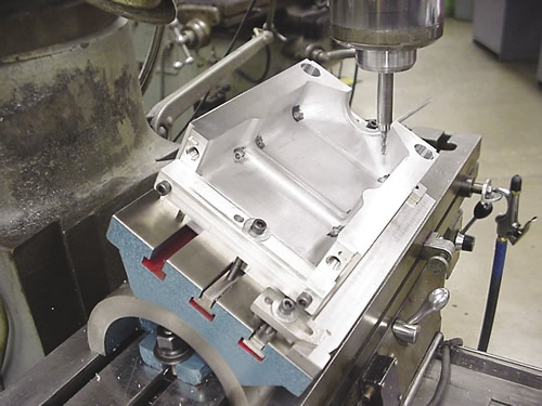
For example, we ran one job on a CNC mill in which we had to put vent pinholes in about a dozen mold cavities. The cavities had to be tilted to get the holes in at the correct angle. We mounted a tooling ball on the cavities at a known location to get a starting point. The holes had to be close in diameter and precise in depth for the vent pins to press into them. The entire operation was risky.
 The next time the job came up, I chose a conventional milling machining to install the vent pinholes. What a relief! It took half the time to install them compared to using the CNC machine—and with a lot less stress. The mold cavities were, of course, machined on a 3-axis CNC machine.
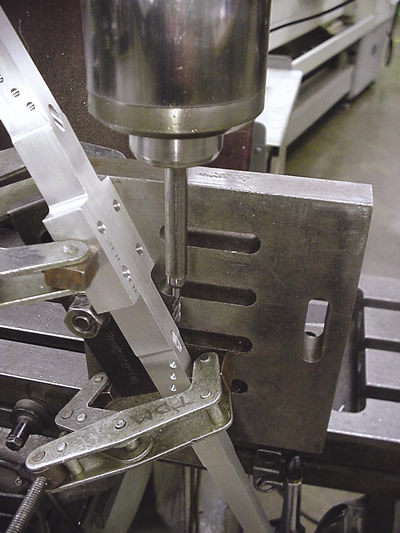
Another job I chose to run on a conventional milling machine is shown on page 38. Again, the holes had to be machined at a fairly extreme angle. The base part, however, was machined on a CNC mill.
In many cases, CNC machines simply are not substitutes for competent machinists.
When using CAM software, the first thing you need is a computer model of a part. The model allows you to apply cutter sizes and other machining parameters such as feeds, speeds and DOC to simulate cutting the model on a computer. Using CAM, you can get a good-but-not-perfect idea on the computer about how the process will run before putting the job on a machine.
CAM applications generate the G code that tells the spindle where to move and how fast to cut using a particular cutting tool. However, generating G code is almost an afterthought because it takes no thinking on your part. Once you’ve chosen toolpaths and input machining parameters, the G code is just a few clicks away.
Automatic programming utilities can be handy, but you’ll still fine-tune the program to get things to run the way you want. I tend to shy away from these utilities at the expense of taking more time initially. I prefer choosing the types and sizes of the cutters myself.
When vendors demonstrate CAM software at trade shows, they can program just about anything in seemingly no time at all, and the part will be cut beautifully on the computer. But you can bet vendors that demonstrate machines actually cutting metal have spent a lot of time fine-tuning their programs.
Related Glossary Terms
- computer numerical control ( CNC)
computer numerical control ( CNC)
Microprocessor-based controller dedicated to a machine tool that permits the creation or modification of parts. Programmed numerical control activates the machine’s servos and spindle drives and controls the various machining operations. See DNC, direct numerical control; NC, numerical control.
- computer-aided manufacturing ( CAM)
computer-aided manufacturing ( CAM)
Use of computers to control machining and manufacturing processes.
- conventional milling ( up milling)
conventional milling ( up milling)
Cutter rotation is opposite that of the feed at the point of contact. Chips are cut at minimal thickness at the initial engagement of the cutter’s teeth with the workpiece and increase to a maximum thickness at the end of engagement. See climb milling.
- gang cutting ( milling)
gang cutting ( milling)
Machining with several cutters mounted on a single arbor, generally for simultaneous cutting.
- milling
milling
Machining operation in which metal or other material is removed by applying power to a rotating cutter. In vertical milling, the cutting tool is mounted vertically on the spindle. In horizontal milling, the cutting tool is mounted horizontally, either directly on the spindle or on an arbor. Horizontal milling is further broken down into conventional milling, where the cutter rotates opposite the direction of feed, or “up” into the workpiece; and climb milling, where the cutter rotates in the direction of feed, or “down” into the workpiece. Milling operations include plane or surface milling, endmilling, facemilling, angle milling, form milling and profiling.
- milling machine ( mill)
milling machine ( mill)
Runs endmills and arbor-mounted milling cutters. Features include a head with a spindle that drives the cutters; a column, knee and table that provide motion in the three Cartesian axes; and a base that supports the components and houses the cutting-fluid pump and reservoir. The work is mounted on the table and fed into the rotating cutter or endmill to accomplish the milling steps; vertical milling machines also feed endmills into the work by means of a spindle-mounted quill. Models range from small manual machines to big bed-type and duplex mills. All take one of three basic forms: vertical, horizontal or convertible horizontal/vertical. Vertical machines may be knee-type (the table is mounted on a knee that can be elevated) or bed-type (the table is securely supported and only moves horizontally). In general, horizontal machines are bigger and more powerful, while vertical machines are lighter but more versatile and easier to set up and operate.
- milling machine ( mill)2
milling machine ( mill)
Runs endmills and arbor-mounted milling cutters. Features include a head with a spindle that drives the cutters; a column, knee and table that provide motion in the three Cartesian axes; and a base that supports the components and houses the cutting-fluid pump and reservoir. The work is mounted on the table and fed into the rotating cutter or endmill to accomplish the milling steps; vertical milling machines also feed endmills into the work by means of a spindle-mounted quill. Models range from small manual machines to big bed-type and duplex mills. All take one of three basic forms: vertical, horizontal or convertible horizontal/vertical. Vertical machines may be knee-type (the table is mounted on a knee that can be elevated) or bed-type (the table is securely supported and only moves horizontally). In general, horizontal machines are bigger and more powerful, while vertical machines are lighter but more versatile and easier to set up and operate.
- turning
turning
Workpiece is held in a chuck, mounted on a face plate or secured between centers and rotated while a cutting tool, normally a single-point tool, is fed into it along its periphery or across its end or face. Takes the form of straight turning (cutting along the periphery of the workpiece); taper turning (creating a taper); step turning (turning different-size diameters on the same work); chamfering (beveling an edge or shoulder); facing (cutting on an end); turning threads (usually external but can be internal); roughing (high-volume metal removal); and finishing (final light cuts). Performed on lathes, turning centers, chucking machines, automatic screw machines and similar machines.


