Centerless Resources
Resources
Centerless Resources
Explore 25 published CTE resources related to Centerless across 6 articles, 13 products, 2 videos, and 4 news items.
6
Articles
13
Products
2
Videos
4
News
Articles
6 articles
Products
13 products
Videos
2 videos
News
4 news items
Browse
Browse all Centerless resources
Browse results
Learn the ins and outs of centerless grinding
Any machinist probably has heard of centerless grinding, but it is an obscure process often only familiar in name.
Get on a roll with centerless grinding
The operation can produce a countless variety of components.
Grinding’s Blackest Art
Centerless grinding is often viewed as overly complex, but a look at the process' fundamentals reveals otherwise.
Thrufeed centerless OD grinding: Parameter relationships and troubleshooting
On many work parts, the outside diameter (OD) needs to be highly accurate. Tight tolerances are required for OD size, roundness, high and low frequency lobe patterns and taper. Thrufeed centerless OD grinding can achieve precise part quality at an economical processing cost.
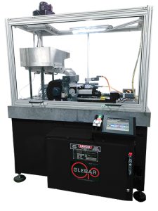
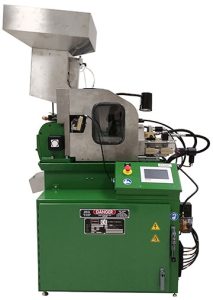
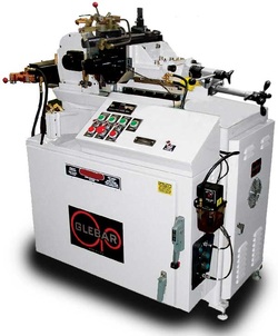
PG-912DG Enclosed Centerless Form Grinder
Glebar pairs the wider work wheel with an oscillating regulating wheel powered by servo motors to reduce setup time and improve sphericity. The slides can be programmed to finite positions through a touchscreen HMI. When an operator selects a job, the servo motors automatically adjust to programmed positions which reduces setup time.
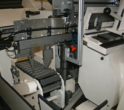
PG-9BHD Centerless Form Grinder
Glebar Co. delivered a solution for grinding deodorant balls while reducing cycle times and improving throughput. Glebar developed ball grinding for the golf ball industry in the 1960s using centerless grinding fundamentals. The process was adapted to grind deodorant balls and other spherical or cylindrically shaped components.
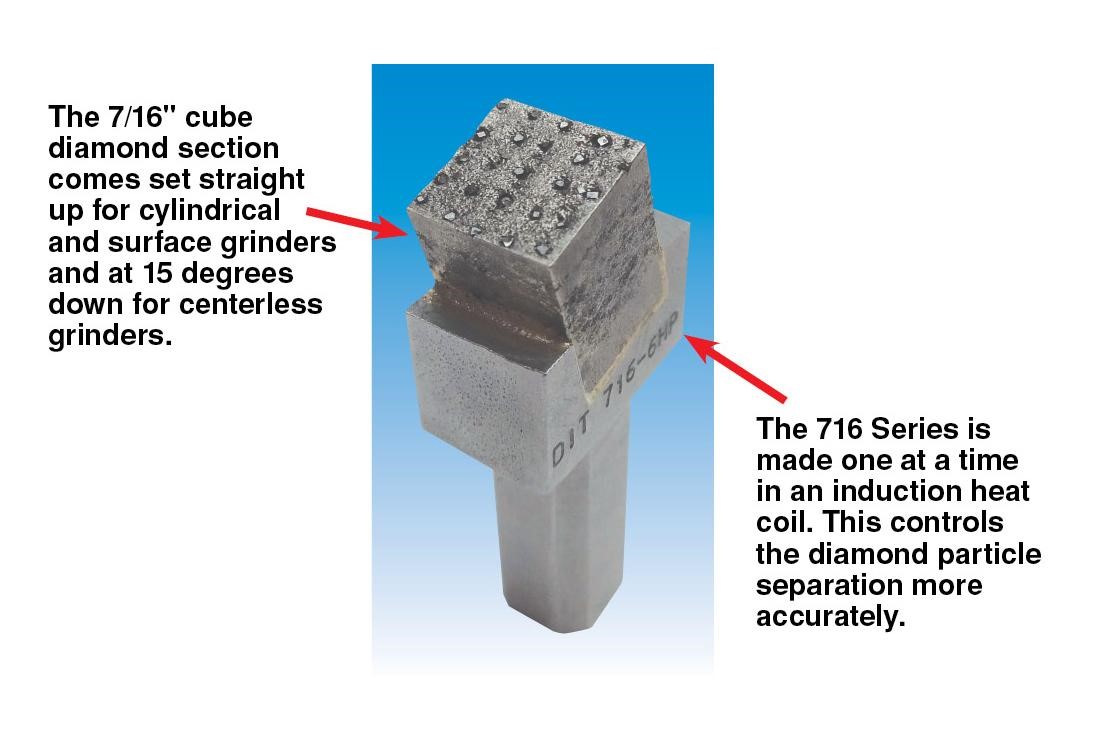
DIT 716 Series Diamond Dressing Tool
Many years ago, the Super 716 Series diamond tool was made for dressing large and wide precision grinding wheels on centerless, cylindrical and surface precision grinding machines. They were made to minimize glazing and the closing up of the wheel surface. They were also made to carry the large wheel without taper or the crushing of the bond.
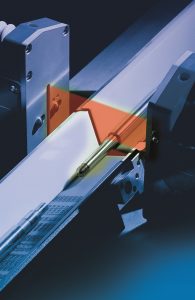
Grindline Laser Measuring System
Marposs offers the Grindline laser measuring system for on-line gauging of parts produced by centerless grinding machines such as pins, shock rods, steering racks or other parts needing a single- or multiple-diameter check. These systems prevent machining of out-of-tolerance pieces to reduce scrap, save time and help companies achieve zero-defect production.
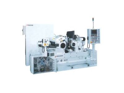
Heavy-Duty, Dual-Support Centerless Grinding Machine
Micron USA's new heavy-duty, dual-support centerless grinder offers 16" (405 mm) wheel width capabilities and twin-grip. This design improves on the company's existing designs and integrates the latest control technology.
GT-610M Centerless Grinding Machine
Glebar Inc. says the GT-610M is an affordable, compact, high-precision centerless infeed/through-feed grinding system, built for the machine shop. The GT-610M includes independent upper and lower slides, and a blade height ramp system for finite blade adjustment.
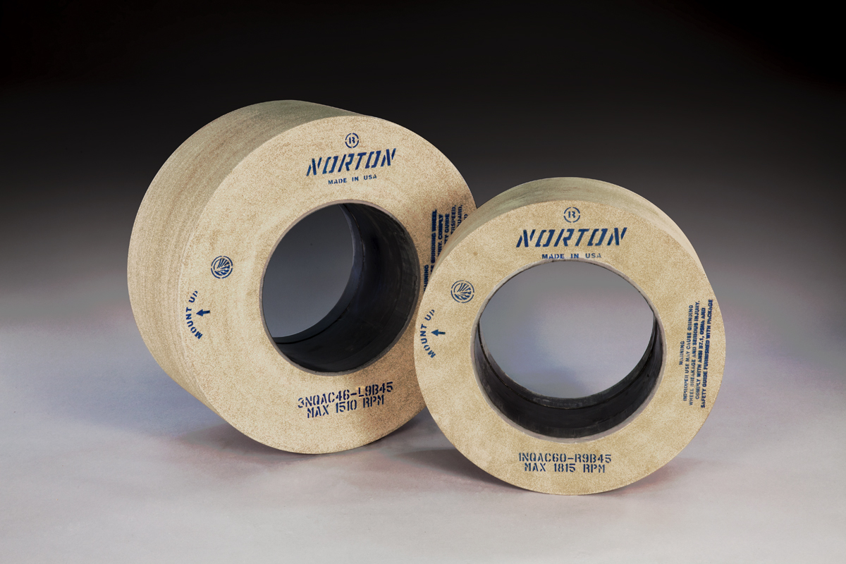
Century45 Centerless Grinding Wheels
Saint-Gobain Abrasives offers a new line of centerless grinding wheels to its bonded abrasives portfolio. The Norton Century45 centerless bond platform features an exclusive chemistry that greatly improves grain retention in the wheel. Better grain retention means wheels are constructed with more porosity for a given hardness.
Flexium CNC Kernel
The grinding specialist RefreshEng has launched a re-engineered centerless grinder based on one of the world's most widely-used machines, with the aid of software development support from CNC vendor NUM.
