On a high-volume production line, the time it takes to loosen and tighten a standard tapholder’s collets or setscrews whenever a tap dulls or breaks can mean lost revenue and missed deadlines. That’s why many shops use quick-change tapping systems. These units can reduce tool-change times from minutes to a few seconds by allowing users to remove and install taps with a simple, easy-to-operate mechanism.
The quick-change mechanism joins two components. One component is the tap adapter, which holds the tap. The other is the tapholder, which is installed in the machine’s spindle. A quick-change mechanism connects the tap adapter to the tap. The operator changes worn or broken taps by removing the tap from the tap adapter and inserting a new tap. If, on the other hand, the tap is broken inside the tap adapter, the tap adapter is removed. In that case, another tap adapter already loaded with a new tap is quickly slipped into the tapholder, and the tapping operation can proceed once again. Both approaches are equally fast, taking 5 seconds at most.
But what if the quick-change tap adapter and tapholder aren’t operating reliably? What if wear and breakage begin to take a high toll on the components? If the components must be replaced frequently, the advantages of quick-change tooling are lost. The cycle time that might have been saved is used, instead, to remove the tool from the tap adapter and load it into a new one or to install a good tapholder in the spindle. To avoid downtime and protect their investment in a quick-change tapping system, shops must take pains to choose a system designed for reliability.
The Weak Link
One of the most likely places for trouble to occur in an unreliable quick-change tapping system is at the point where driving torque is transferred from the tapholder to the tap adapter. During a tapping operation, the cutting forces are concentrated at this point. The most abrupt force is imposed on the system when the tapping process is finished, and the tap is reversed to back it out of the threaded hole.
Over the years, two different designs have emerged to transfer this torque. The older design is the tang drive, which uses two tangs measuring approximately 3¼8" by 1¼8" and spaced 180° apart on the tap adapter. These tangs engage two matching cutouts at the very end of the tapholder.
As many users have found, this type of drive has an inherent weakness. The design demands some measurable clearance between the tangs and the cutouts so the operator can slide the tap adapter into the tapholder with little resistance. Although this clearance is small, in the range of 0.010" to 0.020", and makes the installation of the tap adapter easier, it is enough to allow the two components to move against each other. As this movement occurs during the tapping operation, it causes the tang to crash into the side of the cutout. At the beginning of a tapping operation, the clearance between the tang and the cutout closes up in one direction, slamming the side of the tang against the wall of the tapholder. When the tap is suddenly reversed at the end of the operation, the tang slips in the other direction and slams into the opposite wall of the cutout.
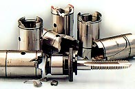
Figure 1: These tapholders were unable to withstand repeated impacts of the tap adapters' tangs against the walls of their cutouts.
These impacts occur at the corner of the cutout. This is also the single point where all of the driving force is concentrated. Under the pressure of these repeated impacts and the concentrated driving force, the corner eventually cracks. In some cases, a section of the tapholder’s wall breaks away (Figure 1). In either case, the tapholder is ruined, and the operator must halt the tapping operation to replace it.
While there are still a considerable number of tang-drive tap adapters in use, a newer ball-drive technology is beginning to dominate the field. This technology was invented by T.M. Smith, founder of T.M. Smith Tool Intl. Corp., Mt. Clemens, MI. Since the expiration of T.M. Smith’s patent, other companies have entered the market with their own versions of the ball-drive quick-change tapholding system.
The original T.M. Smith version employs six steel balls mounted in the tapholder to retain and drive the tap adapter. The balls, which fit into machined detents spaced 60° apart around the base of the tap adapter, are located relatively deep inside the tapholder (Figure 2). To remove or install a tap adapter, the operator pushes back on a knurled shell around the outside of the tapholder. This releases the balls, allowing them to retract to permit the tap adapter to be installed in or removed from the tapholder. When an operator installs a tap adapter into the holder, he inserts it into the front of the holder and then rotates it until the balls click into the detents on the rear of the adapter and the unlocking shell clicks back into its original position. With the balls in their mating detents, the adapter is firmly locked into place.
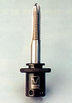
Figure 2: The detents in the base of this tap adapter are designed to receive the steel balls mounted in a ball-drive quick-change tapholder.
The six balls spaced evenly around the inner diameter of the tapholder provide balanced driving torque. This eliminates the problems associated with tang drives, where the driving force is concentrated at the one point of contact between the tang and the cutout. Also, because the balls fit tightly into the detents in the tap adapter, there is no play to allow the system’s components to slam into each other. These advantages allow a ball-drive system to perform reliably even in situations that involve cutting forces too high for a tang-drive system, such as tapping hard-to-machine materials, tapping through inclusions in the workpiece material, or tapping with dulled taps.
Strength and Precision
Ball-drive systems can be damaged, however—especially if they are made of inferior materials. The balls, the tapholder housing, and the body of the adapter are all subject to high forces at the point of contact between each ball and the other components. Consequently, all of these components must be made of properly hardened ball-bearing steel to withstand these forces. Although some manufacturers use softer steels to reduce costs and manufacturing time, a ball-drive system made of these materials will allow the ball to dig into the material, creating a galled or brinelled mating surface, thus preventing the system from functioning properly.
The balls and detents also must be precisely located to match up radially and at the same depth. Without such accuracy, the balls will not fit firmly into the detents.
In the T.M. Smith design, the balls are used for float, thrust, and drive. It is the company’s belief that using balls for these functions produces less friction and wear than other methods, because the ball drive allows the holder to float freely for the full 360°.
A ball-drive quick-change tapping system precisely built of properly hardened ball-bearing steel can be used in any tapping application. With the proper shank, a tapholder can be fitted into the spindle of any manual or CNC tapping machine, drilling machine, milling machine, or lathe.
About the Author
D. Fred Smith is chairman and CEO of T.M. Smith Tool Intl. Corp., Mt. Clemens, MI.
Related Glossary Terms
- clearance
clearance
Space provided behind a tool’s land or relief to prevent rubbing and subsequent premature deterioration of the tool. See land; relief.
- computer numerical control ( CNC)
computer numerical control ( CNC)
Microprocessor-based controller dedicated to a machine tool that permits the creation or modification of parts. Programmed numerical control activates the machine’s servos and spindle drives and controls the various machining operations. See DNC, direct numerical control; NC, numerical control.
- drilling machine ( drill press)
drilling machine ( drill press)
Machine designed to rotate end-cutting tools. Can also be used for reaming, tapping, countersinking, counterboring, spotfacing and boring.
- gang cutting ( milling)
gang cutting ( milling)
Machining with several cutters mounted on a single arbor, generally for simultaneous cutting.
- inner diameter ( ID)
inner diameter ( ID)
Dimension that defines the inside diameter of a cavity or hole. See OD, outer diameter.
- lathe
lathe
Turning machine capable of sawing, milling, grinding, gear-cutting, drilling, reaming, boring, threading, facing, chamfering, grooving, knurling, spinning, parting, necking, taper-cutting, and cam- and eccentric-cutting, as well as step- and straight-turning. Comes in a variety of forms, ranging from manual to semiautomatic to fully automatic, with major types being engine lathes, turning and contouring lathes, turret lathes and numerical-control lathes. The engine lathe consists of a headstock and spindle, tailstock, bed, carriage (complete with apron) and cross slides. Features include gear- (speed) and feed-selector levers, toolpost, compound rest, lead screw and reversing lead screw, threading dial and rapid-traverse lever. Special lathe types include through-the-spindle, camshaft and crankshaft, brake drum and rotor, spinning and gun-barrel machines. Toolroom and bench lathes are used for precision work; the former for tool-and-die work and similar tasks, the latter for small workpieces (instruments, watches), normally without a power feed. Models are typically designated according to their “swing,” or the largest-diameter workpiece that can be rotated; bed length, or the distance between centers; and horsepower generated. See turning machine.
- milling
milling
Machining operation in which metal or other material is removed by applying power to a rotating cutter. In vertical milling, the cutting tool is mounted vertically on the spindle. In horizontal milling, the cutting tool is mounted horizontally, either directly on the spindle or on an arbor. Horizontal milling is further broken down into conventional milling, where the cutter rotates opposite the direction of feed, or “up” into the workpiece; and climb milling, where the cutter rotates in the direction of feed, or “down” into the workpiece. Milling operations include plane or surface milling, endmilling, facemilling, angle milling, form milling and profiling.
- milling machine ( mill)
milling machine ( mill)
Runs endmills and arbor-mounted milling cutters. Features include a head with a spindle that drives the cutters; a column, knee and table that provide motion in the three Cartesian axes; and a base that supports the components and houses the cutting-fluid pump and reservoir. The work is mounted on the table and fed into the rotating cutter or endmill to accomplish the milling steps; vertical milling machines also feed endmills into the work by means of a spindle-mounted quill. Models range from small manual machines to big bed-type and duplex mills. All take one of three basic forms: vertical, horizontal or convertible horizontal/vertical. Vertical machines may be knee-type (the table is mounted on a knee that can be elevated) or bed-type (the table is securely supported and only moves horizontally). In general, horizontal machines are bigger and more powerful, while vertical machines are lighter but more versatile and easier to set up and operate.
- shank
shank
Main body of a tool; the portion of a drill or similar end-held tool that fits into a collet, chuck or similar mounting device.
- tang
tang
Extended flat portion of tapered drill shank, endmill or other tool that allows maximum power transmission and proper positioning of the tool. Reverse shape of the machine-spindle slot into which it fits.
- tap
tap
Cylindrical tool that cuts internal threads and has flutes to remove chips and carry tapping fluid to the point of cut. Normally used on a drill press or tapping machine but also may be operated manually. See tapping.
- tapping
tapping
Machining operation in which a tap, with teeth on its periphery, cuts internal threads in a predrilled hole having a smaller diameter than the tap diameter. Threads are formed by a combined rotary and axial-relative motion between tap and workpiece. See tap.
- tapping machine
tapping machine
Production machine used for high-volume tapping. Offers repeatability, high production rates and reduced tap breakage. Comes in a variety of configurations, including indexing units with multiple tapping spindles. Precise stroke-depth settings and automatic features generally make tapping machines cost-effective.