Every lathe and grinder operator has, at one time or another, struggled with workpieces that are out of round, tapered or have poor finish. The "quick fix " is typically replacing centers. The more involved fix requires replacing spindle bearings that appear to have failed prematurely. In either case, the problem goes away initially, only to reoccur a short time later.
In time, and after needless downtime and material and labor costs, it will become obvious that these measures are treating the symptoms, not the root causes of rejected parts. For the purposes of this column, let 's assume the cutting tools or grinding wheel are appropriate to the task, that the workpiece center hole is appropriately sized, and the center (live or dead) is suitable for the machine and load.
Without those issues as possible culprits, what’s left are the two basic factors that control part quality in turning and grinding applications: machine alignment and rigidity.
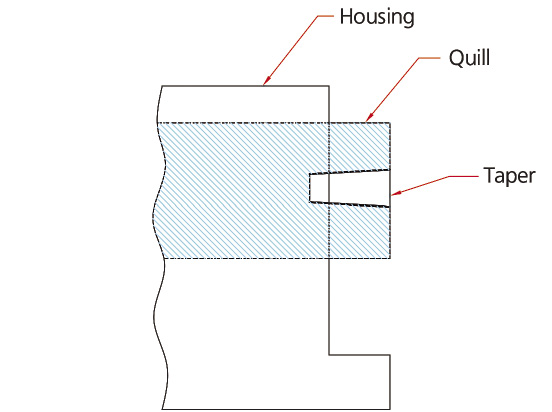
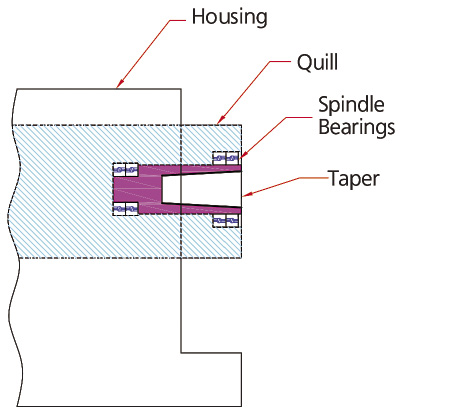
Figure 1. Dead tailstock. Figure 2. Live tailstock.
Machine alignment can be a maintenance issue, and maintenance personnel should ensure the headstock and the tailstock are properly aligned. Trained operators can make adjustments for taper if the machine allows such changes.
Rigidity is defined as a machine 's ability to hold a workpiece solidly on center. A lack of rigidity is by far the most common—and the most overlooked—cause of bad parts. Several machine components either contact the workpiece directly or affect the accuracy (concentricity) of its rotation.
The headstock, with its large size and heavy bearings, is not typically the root cause. The tailstock, however, is usually smaller and therefore the more likely source of trouble. Specifically, wear and tear on critical components of the tailstock can be the root cause of poor rigidity.
Dead tailstocks consist of a housing and quill with a mounting taper (Figure 1). The taper is commonly a Morse taper, but Jarno and Brown & Sharpe tapers are found on some machines. Live tailstocks add a rotating spindle with bearings to the assembly (Figure 2). Lathes with dead tailstocks require a live center while live tailstocks require a dead center. Because grinders rotate at lower speeds, they may employ live or dead centers in either style of tailstock.
When dead tailstocks are sent in for repair, the mounting taper is inspected first. The center must fit snugly—the industry standard requires a minimum of 90 percent contact between the taper shank and the mounting taper, with minimal gaps or constrictions. Excessive wear is a primary reason when centers don 't fit firmly.
Properly done, bluing the ID with a taper gage will highlight out-of-roundness or other visible damage to the taper (Figure 3). The bluing should be at least 90 percent visible on all surfaces. Any large gaps or heavy bluing are sure signs of a deformed taper.
Even if the taper is in poor condition, it is a good practice to make further checks. The runout between the taper ID and the quill OD should be measured to ensure alignment is within specifications. This is a check for concentricity to ensure that the taper is centered exactly within the quill. Finally, the quill OD and the housing ID should be checked for size and roundness. It is critical for the quill to fit properly in the housing.
Inspection of live tailstocks includes all the previous steps, but the rotating spindle adds another layer of complexity. The spindle is a primary load-bearing element and should be checked for visible damage, such as wear and cracks. The bearings journals should be scrutinized for wear, size and concentricity. The quill’s ID needs to be carefully inspected for size and roundness to ensure the new spindle bearings will fit properly. The key word in all these checks is “fit.”
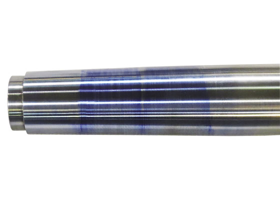
Figure 3. Bluing on a taper gage should be light and even (above). Heavy bluing indicates the taper did not contact the quill interior, while gaps mean the fit was too tight (below).
Riten recently received an extremely large live quill for repair after the bearings had failed to the point that the spindle would no longer rotate. It was part of a roll lathe that turned parts weighing 10,000 to 30,000 lbs.
Although the source of the problem was evident, Riten went through the complete inspection procedure in case there were additional issues. The findings were reported to the customer along with the cost and estimated time to complete the repair.
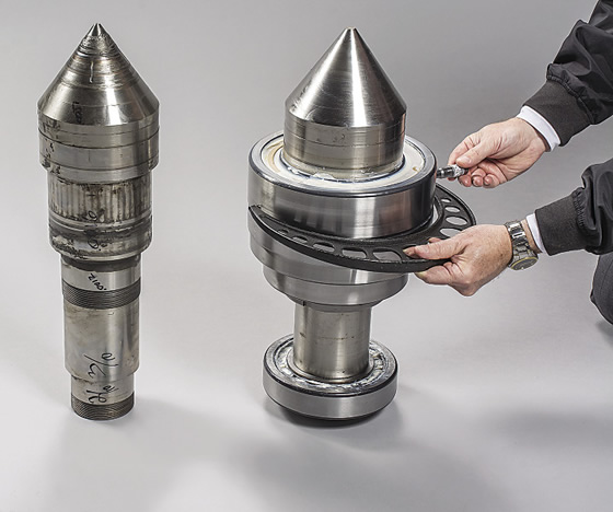
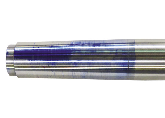
Figure 4a (left). A damaged spindle as received, with failed bearings removed. Figure 4b (right). The remanufactured spindle with new bearings installed.
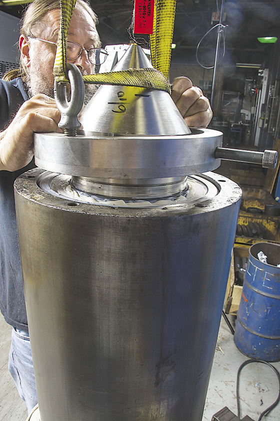
Figure 5. The new spindle is lowered into the repaired quill, achieving a slip fit.
Surprisingly, the taper, in this case a 60° point, had only minor wear, but the spindle bearings were irreparably damaged (Figure 4a). There was also noticeable wear to the bearing seats on the quill ID, indicating the bearings were not seating properly. There was also obvious wear on the spindle bearing journals. Running the lathe to the point of catastrophic bearing failure damaged both the quill and the spindle.
The most economical solution was to remanufacture the spindle bearing journals and lightly grind the taper to remove wear and restore concentricity to the new bearing surfaces. Magnetic particle inspection of the rebuilt spindle was performed to ensure its structural integrity. New bearings were installed, making sure they were matched for size and correctly mounted (Figure 4b).
Because the damage to the quill ID was extensive, it was turned oversize and a bushing was manufactured. Once the bushing was installed, the new bearing surfaces were ground to the proper size. Care was taken to maintain concentricity between the bearing ID and the quill OD.
The final step in the process was inserting the new spindle and bearing assembly into the quill. On smaller quills, a simple press fit is usually sufficient. However, in this instance, the housing was more than 5 ' long, so a more complex slip-fit procedure was required. The spindle was encased in dry ice while a heater was inserted into the quill. During this process, the spindle shrinks and the housing expands. The spindle was then lowered into the quill (Figure 5), and when both were returned to ambient temperature, a precise fit was accomplished. The completed tailstock was then tested to ensure the bearings were functioning properly.
The first signs of excessive bearing wear are noise and elevated temperatures. At this point, a routine bearing replacement should be considered. Ignoring these signs will lead to catastrophic bearing failure and a more costly repair and rebuilding process. CTE
Related Glossary Terms
- bushing
bushing
Cylindrical sleeve, typically made from high-grade tool steel, inserted into a jig fixture to guide cutting tools. There are three main types: renewable, used in liners that in turn are installed in the jig; press-fit, installed directly in the jig for short production runs; and liner (or master), installed permanently in a jig to receive renewable bushing.
- centers
centers
Cone-shaped pins that support a workpiece by one or two ends during machining. The centers fit into holes drilled in the workpiece ends. Centers that turn with the workpiece are called “live” centers; those that do not are called “dead” centers.
- grinding
grinding
Machining operation in which material is removed from the workpiece by a powered abrasive wheel, stone, belt, paste, sheet, compound, slurry, etc. Takes various forms: surface grinding (creates flat and/or squared surfaces); cylindrical grinding (for external cylindrical and tapered shapes, fillets, undercuts, etc.); centerless grinding; chamfering; thread and form grinding; tool and cutter grinding; offhand grinding; lapping and polishing (grinding with extremely fine grits to create ultrasmooth surfaces); honing; and disc grinding.
- grinding wheel
grinding wheel
Wheel formed from abrasive material mixed in a suitable matrix. Takes a variety of shapes but falls into two basic categories: one that cuts on its periphery, as in reciprocating grinding, and one that cuts on its side or face, as in tool and cutter grinding.
- inner diameter ( ID)
inner diameter ( ID)
Dimension that defines the inside diameter of a cavity or hole. See OD, outer diameter.
- lathe
lathe
Turning machine capable of sawing, milling, grinding, gear-cutting, drilling, reaming, boring, threading, facing, chamfering, grooving, knurling, spinning, parting, necking, taper-cutting, and cam- and eccentric-cutting, as well as step- and straight-turning. Comes in a variety of forms, ranging from manual to semiautomatic to fully automatic, with major types being engine lathes, turning and contouring lathes, turret lathes and numerical-control lathes. The engine lathe consists of a headstock and spindle, tailstock, bed, carriage (complete with apron) and cross slides. Features include gear- (speed) and feed-selector levers, toolpost, compound rest, lead screw and reversing lead screw, threading dial and rapid-traverse lever. Special lathe types include through-the-spindle, camshaft and crankshaft, brake drum and rotor, spinning and gun-barrel machines. Toolroom and bench lathes are used for precision work; the former for tool-and-die work and similar tasks, the latter for small workpieces (instruments, watches), normally without a power feed. Models are typically designated according to their “swing,” or the largest-diameter workpiece that can be rotated; bed length, or the distance between centers; and horsepower generated. See turning machine.
- outer diameter ( OD)
outer diameter ( OD)
Dimension that defines the exterior diameter of a cylindrical or round part. See ID, inner diameter.
- shank
shank
Main body of a tool; the portion of a drill or similar end-held tool that fits into a collet, chuck or similar mounting device.
- turning
turning
Workpiece is held in a chuck, mounted on a face plate or secured between centers and rotated while a cutting tool, normally a single-point tool, is fed into it along its periphery or across its end or face. Takes the form of straight turning (cutting along the periphery of the workpiece); taper turning (creating a taper); step turning (turning different-size diameters on the same work); chamfering (beveling an edge or shoulder); facing (cutting on an end); turning threads (usually external but can be internal); roughing (high-volume metal removal); and finishing (final light cuts). Performed on lathes, turning centers, chucking machines, automatic screw machines and similar machines.