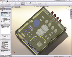
SolidWorks 2009 Premium is the newest version of Dassault Systèmes SolidWorks Corp.’s 3-D CAD software, which offers capabilities for manufacturers, designers and engineers. Those capabilities include enhanced importing and repairing of data, drawing and assembly, and the ability to check designs for accurate tooling.
For many years, the vast majority of machine shops have gone without any CAD software at all. Instead, CAM applications have been the mainstays for tooling, machining and manufacturing operations. CAM continues to drive toolpath programming for CNC machining.

Courtesy of SolidWorks
SolidWorks 2009 adds a new quality capability, “assembly clearance verification,” that enhances interference checking and hole alignment by adding the ability to design for necessary clearances.
However, in today’s economic climate, machine shops are looking to reduce costs and improve productivity. As a result, many are installing 3-D CAD systems because they can no longer afford to process and reprocess customer geometry, create tooling from square one and program CNC code. A 3-D CAD system:
• Improves handling of part models. With a 3-D CAD system, machine shops can import, repair and revise models in a variety of design data formats. They can assess a model’s manufacturability, eliminate errors and reduce waste, scrap and rework.
• Automates design changes. Changes occur in most designs, and a 3-D CAD system can automate the process of changing the model and reprogramming the toolpath in the CAM system.
• Better communicates changes and production issues. The visualization capabilities in a 3-D CAD system make it easier to communicate the nature and reason for required changes.
• Enhances jig and fixturing design. With a 3-D CAD program, machinists can use the part model as a template for designing the manufacturing environment, including jigs, chucks and fixturing.
SolidWorks offers Certified Gold Partner status integrations with many of the industry’s leading manufacturing/CAM software products, such as CAMWorks from Geometric Technologies Inc., HSMWorks from HSMWorks ApS, hyperMILL in SolidWorks from Open Mind Technologies AG and SolidCAM from SolidCAM Ltd. Integrating CAM packages with SolidWorks is intended to improve productivity and speed to market.
“Many machine shops contend that they cannot afford an integrated CAD/CAM system,” said Dennis Waite, shop manager of Deka Research & Development Corp., Manchester, N.H., a contract machine shop that uses the integrated SolidWorks/SolidCAM CAD/CAM system. “But from our position in the market, we have determined that we cannot afford to operate without an integrated CAD/CAM system. We realize benefits at almost every phase of the process, resulting in operating cost savings that make us more competitive.”
Concerning speed, the new version of SolidWorks 2009 has a documented speed increase of up to 65 percent over SolidWorks 2008.
Machine shops need to be able to read and repair data. In SolidWorks 2009, there is an added enhancement to manipulate imported geometry called “instant editing,” which allows users to click on a geometry and move it.
Many machine shops prefer to work with 2-D drawings, so SolidWorks 2009 has drawing enhancements like the new “title block wizard.” It automates the creation, editing and standardization of title block information.
The “dimension jog” capability allows users to make drawing details clearer and easier to interpret. The software also now enables previewing of a drawing before committing to open it using “quick view.” After a user previews the desired drawing sheet, he can open it with “load sheet,” which only loads that one sheet into memory.
Designing in 3-D provides the ability to check interferences and clearances in a design to ensure that when manufacturing parts, the assemblies will fit together correctly the first time. SolidWorks 2009 adds a new quality capability, “assembly clearance verification,” that enhances interference checking and hole alignment by adding the ability to design for necessary clearances.
SolidWorks also provides premade solid models for machine shop designers. They’re available online at 3DContentCentral.com or directly inside SolidWorks’ design library. When adding a fastener from “toolbox,” a part of the design library, SolidWorks 2009 ensures that the correct length of fastener is included in the design.
SolidWorks 2009 also supplies single-window, fully associative integration with SolidWorks simulation, data management and 3-D content collaboration products. CTE
About the Author: Fielder Hiss is director of product management of Dassault Systèmes SolidWorks Corp., Concord, Mass. For more information about the company’s CAD software, e-mail [email protected], call (800) 693-9000, visit www.solidworks.com or enter #310 on the IS Form.
Related Glossary Terms
- 2-D
2-D
Way of displaying real-world objects on a flat surface, showing only height and width. This system uses only the X and Y axes.
- 3-D
3-D
Way of displaying real-world objects in a natural way by showing depth, height and width. This system uses the X, Y and Z axes.
- clearance
clearance
Space provided behind a tool’s land or relief to prevent rubbing and subsequent premature deterioration of the tool. See land; relief.
- computer numerical control ( CNC)
computer numerical control ( CNC)
Microprocessor-based controller dedicated to a machine tool that permits the creation or modification of parts. Programmed numerical control activates the machine’s servos and spindle drives and controls the various machining operations. See DNC, direct numerical control; NC, numerical control.
- computer-aided design ( CAD)
computer-aided design ( CAD)
Product-design functions performed with the help of computers and special software.
- computer-aided manufacturing ( CAM)
computer-aided manufacturing ( CAM)
Use of computers to control machining and manufacturing processes.
- jig
jig
Tooling usually considered to be a stationary apparatus. A jig assists in the assembly or manufacture of a part or device. It holds the workpiece while guiding the cutting tool with a bushing. A jig used in subassembly or final assembly might provide assembly aids such as alignments and adjustments. See fixture.
- toolpath( cutter path)
toolpath( cutter path)
2-D or 3-D path generated by program code or a CAM system and followed by tool when machining a part.
