Technological advancements have made superabrasive bore finishing the best method for achieving excellent finishes in both through and blind bores.
Shops that have made the move from conventional bore honing to single-pass superabrasive bore finishing have reaped several benefits: automated finishing, which yields lower labor costs; long tool life, which lowers cost per hole; predictable, consistent results that lend themselves to quality-control management; fewer rejects; less frequent part inspection; and high production rates. Recent technical advancements have made the process the most cost-effective choice for virtually any bore-finishing application (other than for short runs of under 50 parts) and for virtually any workpiece material (other than titanium alloys). These advancements permit automatic tool-size compensation and allow superabrasive finishing tools to finish blind and semiblind bores and produce bore geometries to within 0.000020".
Superabrasive bore finishing is performed with barrel-shaped tools coated with either diamond or cubic-boron-nitride (CBN) pArticles. After an initial break-in period, the tools need occasional size adjustments only to compensate for diamond wear. The tool is passed once through a bore while the tool, the part, or both rotate. In contrast, a conventional hone expands and contracts with each cycle and is involved in three mechanical processes that take place simultaneously - abrasive stone feed, rotation, and reciprocation (Figure 1). Reciprocation refers to the action of the tool entering the bore, then repetitively feeding up-and-down through the bore several times, and finally withdrawing from the bore. Since superabrasive bore-finishing tools don’t have to expand and contract during each cycle and don’t wear as quickly as conventional hones, they do a better job of maintaining tight control of the bore size. And the simplicity of superabrasive bore finishing makes the process quicker and more accurate than conventional honing.
The front portion of a single-pass tool is designed with enough taper to let the tool enter the existing bore. Once the tool has entered the bore, a specific amount of work material is removed along the remaining length of the tool. Since this material is gradually removed by the thousands of superabrasive pArticles surrounding the tool’s periphery, very little heat or stress is generated. The heat and stress are absorbed and dissipated by the multitude of pArticles. This prevents the bore distortion that can result when a tool cannot cut freely.
Surface-Finish Capability
Stock-removal and surface-finish capabilities are directly related to the size of the superabrasive pArticles used on a particular tool. For example, a 100-grit tool can generally remove up to 0.003" of stock in gray cast iron and achieve a 60µin. to 80µin. surface finish. Conversely, a 400-grit tool in the same material could produce a much finer finish but only be able to remove a maximum of 0.001" stock.
The same principle also applies when finishing other materials. For example, in hardened steel a 100-grit tool may be able to remove 0.0008" of material and achieve a 40µin. finish. A 400-grit tool in the same material could produce a surface finish as low as 10µin., but it would be held to a much lower stock-removal rate. Table 1 shows the stock-removal capabilities of different superabrasive grits machining various workpiece materials. Table 2 shows surface-finish capabilities for the same grit/workpiece combinations.
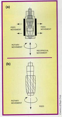
| Figure 1: | The mechanical movements of a conventional honing tool (a) vs. those of a single-pass superabrasive tool (b). |
Because of this phenomenon, many applications require the use of a series of preset, single-pass tools - a multitool operation. The tools are set up sequentially in different stations, much the way conventional hones would be. The single-pass process maintains an advantage over conventional honing in this case because it uses plated diamond and CBN, which last much longer than conventional tool materials. For example, in cast iron a superabrasive single-pass tool may finish more than 100,000 to 250,000 bores before requiring replacement. In a multitool operation, each tool is set to remove its share of the total material in ever-diminishing amounts as the part is brought to size. Coarse-grit tools are used for the initial material-removal stages, and then fine-grit tools are used to achieve the desired finish.
Size Compensation
Along with needing several superabrasive grits to choose from, users also require an array of tool styles with different manual and automatic size-adjustment mechanisms to cover the wide range of applications that call for precision bore finishing (Figure 2). The following are examples of mandrel designs, each characterized by its individual adjusting features:
One-Piece Mandrel: To increase size, the superabrasive sleeve, which has a tapered bore and is split on a helix, must be physically repositioned up the mating taper on the mandrel by use of a brass hammer. Adjusting size in increments smaller than 0.0001" can be tricky. To reduce size, the sleeve must be tapped down the taper in the opposite direction. Therefore, the one-piece mandrel design is recommended only when other types are not available, such as in very small sizes.
|
DIAMETRICAL STOCK REMOVAL |
|||||
| Material | 60 Grit | 100 Grit | 220 Grit | 400 Grit | 600 Grit |
| Cast Iron/Powdered Metal | 0.0040" (0.101mm) |
0.0030" (0.076mm) |
0.0020" (0.051mm) |
0.0010" (0.025mm) |
0.0005" (0.012mm) |
| Soft Steel | 0.0015" (0.038mm) |
0.0012" (0.030mm) |
0.0007" (0.018mm) |
0.0005" (0.012mm) |
0.0002" (0.005mm) |
| Hard Steel | 0.0010" (0.025mm) |
0.0008" (0.020mm) |
0.0005" (0.012mm) |
0.0002" (0.005mm) |
0.0002" (0.005mm) |
| Aluminum | 0.0030" (0.076mm) |
0.0020" (0.051mm) |
0.0015" (0.038mm) |
0.0005" (0.012mm) |
0.0003" (0.008mm) |
| Ceramic | 0.0050" (0.127mm) |
0.0040" (0.101mm) |
0.0025" (0.063mm) |
0.0005" (0.012mm) |
0.0005" (0.012mm) |
Table 1: Approximate stock-removal capabilities of various superabrasive grits machining various workpiece materials.
|
SURFACE FINISH - MICROINCH (MICROMETER) |
|||||
| Material | 60 Grit | 100 Grit | 220 Grit | 400 Grit | 600 Grit |
| Cast Iron/Powdered Metal | 148 Ra (3.70) Ra |
80 Ra (2.00) Ra |
32 Ra (0.80) Ra |
16 Ra (0.40) Ra |
12 Ra (0.30) Ra |
| Soft Steel | 100 Ra (2.50) Ra |
70 Ra (1.75) Ra |
32 Ra (0.80) Ra |
16 Ra (0.40) Ra |
12 Ra (0.30) Ra |
| Hard Steel | 64 Ra (1.60) Ra |
48 Ra (1.20) Ra |
20 Ra (0.50) Ra |
10 Ra (0.25) Ra |
8 Ra (0.20) Ra |
| Aluminum | 148 Ra (3.70) Ra |
80 Ra (2.00) Ra |
32 Ra (0.80) Ra |
16 Ra (0.40) Ra |
12 Ra (0.30) Ra |
| Ceramic | 148 Ra (3.70) Ra |
84 Ra (2.10) Ra |
40 Ra (1.00) Ra |
20 Ra (0.50) Ra |
16 Ra (0.40) Ra |
Table 2: Approximate surface-finish capabilities of various superabrasive grits machining various workpiece materials.
Front-Adjusting Mandrel: With this design, size can be increased by means of a pilot nut in the front of the tool. Each turn of this nut moves the superabrasive sleeve up the mating taper of the mandrel, thus expanding the size a specific, controllable amount. As with the one-piece mandrel, the sleeve must be tapped down the taper in the opposite direction to reduce size. However, this mandrel’s front-adjusting nut is calibrated, making precise sizing easier and oversizing rarer. This makes the need to reduce size less common.
Dual-Adjusting Mandrel: As with the front-adjusting mandrel, size is expanded by use of a front pilot nut. With this design, however, size can also be reduced by means of an additional adjusting nut located behind the superabrasive sleeve.
Reverse-Taper Mandrel: As the name implies, the taper on this mandrel runs the opposite direction (small in back, larger in front), so that the size can be increased or decreased by means of adjusting nuts behind the sleeve. As with the front-adjusting mandrel, the nut is calibrated for more precise sizing. This design is used when clearance behind the bore to be finished is restricted, such as in semiblind applications.
Automatic-Expansion Mandrel: This advanced design allows size to be expanded automatically when needed by the machine tool without stopping production. This is achieved by allowing a male and female hex connection to be made between the superabrasive tool and the machine tool. Because the machine can expand the tool precisely as needed, reducing the tool size is rarely required. The machine tool can be prompted by an in-process or post-process gage to tell it when tool compensation is needed. The hex fitting is then rotated a specific amount, which mechanically expands the cutting portion of the tool. This design is used on high-production transfer machines and can be incorporated only into special-purpose machines, in which the finishing, gaging, loading, and unloading functions are designed around one particular part.
When installing a new tool, the following procedure is commonly used to achieve the correct tool size:
- Set the size approximately via a micrometer or a ring gage.
- Bore finish the part in a single pass and check the size of the bore.
- Expand the tool.
- Repeat steps 2 and 3 as often as needed until the tools are producing the desired size, taking care not to bore oversize.
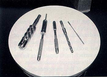 |
Figure 2: Single-pass superabrasive tools feature a variety of styles to fit a variety of applications and user needs. |
Once the tool’s size is set, a break-in period is likely for the first 100 or so parts. During this period, size may have to be adjusted frequently due to the sharp peaks of the superabrasive grains wearing down.
This condition is generally accepted as being normal. The subsequently long tool life, with short cycle times, more than makes up for the downtime experienced initially. Besides, as cumbersome as this process may seem, it has to be done only at the beginning of a part run. With conventional tools, size must be adjusted frequently throughout a run and throughout the life of the tool.
However, some users, because of demands for increased production, have found it necessary to minimize the procedure described above. To do this, special presized, preconditioned tooling has been developed. The tool manufacturer assembles, conditions, and brings to size a specific tool prior to shipment. To ensure proper size, a test piece or coupon is bore finished using the preset tool, and the bore is measured to verify the tool size. If the tool passes this test, the operator can install it, much as he would a reamer, and start running on-size parts almost immediately. Then, when needed, size can be adjusted to compensate for tool wear.
Blind-Bore Finishing
Not long ago, many thought that the single-pass process was not capable of semiblind-bore finishing. However, with recent improvements such as free-floating fixtures, machines with servo control and positional feedback for accurate depth, and tools that can expand from the nose, single-pass bore finishing has actually become the preferred method of finishing bores with clearance restrictions as low as 0.1" (Figure 3).
Bore geometries held within better than 0.0001", with surface finishes below 16µin., are now obtainable in a variety of workpiece materials, including hardened steel, at production rates of up to 360 pieces/hr. By contrast, conventional honing of blind bores is difficult at best. Size control and bore quality are generally poor.
To work properly, the superabrasive tooling must be made with an extremely short lead-in taper to clear the bore walls. Because of this, more tools may be necessary in a semiblind bore setup than a through-hole setup to remove the same amount of material. Also, location of the part’s bore, relative to the centerline of the tool, becomes even more critical. The use of a fixture that floats both radially and axially may be required in some materials. For example, in hardened steel, the stock-removal rates are already relatively low, so any misalignment in the part could cause the tool to seize because of the added pressure. A floating fixture can prevent misalignment.
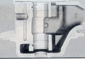 |
Figure 3: Cut-away of a part displaying a finished 0.983"-dia. semiblind bore. Total clearance behind the bore is 0.100". |
Even with the best tool layout and fixture design, if the machine tool used is not capable of accurately and repeatedly positioning the superabrasive tools, the process may not work. A machine tool with CNC program capabilities and accurate servomotor-fed spindle columns is recommended.
Tight Geometries
As the demand for greater precision increases, the need to produce bore geometries to tolerances of 0.000020" or less in production will become more common. While sometimes hard to measure, and often hard to imagine, this type of precision can be achieved in production from the single-pass bore-finishing process under the right conditions.
First, one must have a good tooling plan and design that take into account the workpiece material, hardness, and lot-to-lot variation; bore size, length, and shape (e.g., solid or interrupted); the part’s wall thickness; and finish requirements.
Second, the part must be presented to the superabrasive tooling in such a way that the least amount of force is needed for the tool to follow the centerline of the part’s existing bore. Because of variances in the part’s bore location, index table precision, spindle accuracy, and the part’s fixture positioning, using a standard floating toolholder with a securely held part will not usually suffice. Although a floating toolholder will allow the tool to reposition itself up to a few thousandths of an inch, the forces involved are usually enough to lose the desired 0.000020" bore precision.
Because of their free-floating characteristics, double universal toolholders, which have two swivel joints that allow the tool to pivot and move about freely, are sometimes used, often with very good results. On the downside, because of centrifugal force, these toolholders tend to "whip" at higher spindle speeds. That characteristic makes these toolholders impractical for smaller diameter bores.
The best results have been obtained by using a standard floating holder in conjunction with a free-floating gimbal part fixture. A gimbal fixture’s inner ring pivots and slides along two pins. The middle ring pivots and slides along two pins located 90 from the inner ring’s pin so that there is complete free-floating movement in all directions. Bearings are sometimes used to reduce friction. The pivot point is usually designed to be in the axial center of the bore being finished. This fixture allows the existing bore to both radially and axially float so that perfect alignment is possible with only slight forces involved.
The third condition that must be met is that the part must be held in a way that does not distort the bore. For example, on a thin-walled cylindrical part, a collet fixture could collapse the bore to a certain degree while the part is engaged for finishing. After the part is released, the bore would spring back and ruin the accuracy the tool had just achieved.
Usually it is best to hold a part loosely and utilize a feature on the part, such as a flat or notch, as an area to engage to prevent rotation. This also brings back into account the importance of the tooling plan in which the stock removal of each tool is limited by the forces allowable by the particular part and fixture method without creating any bore distortion.
Single-pass superabrasive bore finishing has proven to be a very effective means of precision finishing part IDs. Not only can the process hold extremely tight tolerances in a production environment, but it also costs less per finished piece than conventional honing does.
About the Author
Robert Marvin is production manager at Engis Corp., Wheeling, IL.
Related Glossary Terms
- abrasive
abrasive
Substance used for grinding, honing, lapping, superfinishing and polishing. Examples include garnet, emery, corundum, silicon carbide, cubic boron nitride and diamond in various grit sizes.
- clearance
clearance
Space provided behind a tool’s land or relief to prevent rubbing and subsequent premature deterioration of the tool. See land; relief.
- collet
collet
Flexible-sided device that secures a tool or workpiece. Similar in function to a chuck, but can accommodate only a narrow size range. Typically provides greater gripping force and precision than a chuck. See chuck.
- computer numerical control ( CNC)
computer numerical control ( CNC)
Microprocessor-based controller dedicated to a machine tool that permits the creation or modification of parts. Programmed numerical control activates the machine’s servos and spindle drives and controls the various machining operations. See DNC, direct numerical control; NC, numerical control.
- cubic boron nitride ( CBN)
cubic boron nitride ( CBN)
Crystal manufactured from boron nitride under high pressure and temperature. Used to cut hard-to-machine ferrous and nickel-base materials up to 70 HRC. Second hardest material after diamond. See superabrasive tools.
- feed
feed
Rate of change of position of the tool as a whole, relative to the workpiece while cutting.
- fixture
fixture
Device, often made in-house, that holds a specific workpiece. See jig; modular fixturing.
- flat ( screw flat)
flat ( screw flat)
Flat surface machined into the shank of a cutting tool for enhanced holding of the tool.
- hardness
hardness
Hardness is a measure of the resistance of a material to surface indentation or abrasion. There is no absolute scale for hardness. In order to express hardness quantitatively, each type of test has its own scale, which defines hardness. Indentation hardness obtained through static methods is measured by Brinell, Rockwell, Vickers and Knoop tests. Hardness without indentation is measured by a dynamic method, known as the Scleroscope test.
- mandrel
mandrel
Workholder for turning that fits inside hollow workpieces. Types available include expanding, pin and threaded.
- micrometer
micrometer
A precision instrument with a spindle moved by a finely threaded screw that is used for measuring thickness and short lengths.
- reamer
reamer
Rotating cutting tool used to enlarge a drilled hole to size. Normally removes only a small amount of stock. The workpiece supports the multiple-edge cutting tool. Also for contouring an existing hole.
- superabrasive tools
superabrasive tools
Abrasive tools made from diamond or cubic boron nitride, the hardest materials known. See CBN, cubic boron nitride; diamond; PCD, polycrystalline diamond; single-crystal diamond.
- through-hole
through-hole
Hole or cavity cut in a solid shape that connects with other holes or extends all the way through the workpiece.
- toolholder
toolholder
Secures a cutting tool during a machining operation. Basic types include block, cartridge, chuck, collet, fixed, modular, quick-change and rotating.