Machine tool operators who understand why drills break are better equipped to improve the efficiency of their holemaking operations.
Itąs not surprising that holemaking accounts for more machining time than other metalworking operations. Almost every part has bores, bolt holes, and other round and cylindrical features that must be machined into it.
Itąs also not surprising that reducing holemaking costs is an important consideration in reducing overall production costs. Holemaking accounts for a large percentage of the total cost of manufacturing, and any reduction in these costs has a large impact on operating expenses. One of the primary ways to cut holemaking costs is to reduce drill breakage and premature wear.
Drill breakage is the most common problem associated with holemaking operations, and it is a major cause of machine tool downtime. When a drill breaks, it must be removed from the workpiece using another drilling operation. This wastes valuable production time and can produce out-of-tolerance holes, scarred surface finishes, and other quality problems in the finished component.
Premature drill wear also reduces the efficiency of holemaking operations. Typically, a drill wears too fast when the operator has chosen a speed and feed rate that are too low for the application. The result is ineffective chipbreaking, which creates surface scarring. In some cases, slow speeds and feeds have the effect of burnishing the hole, creating unwanted bright spots. Premature wear also can lead to drill breakage: When the cutting edge wears thin, it breaks.
The causes of drill breakage and premature wear are many and varied, and even experienced machine tool operators can fall victim to the unique problems that affect drill performance. There are ways to keep breakage under control, however, and understanding why a drill breaks will help.
Coolant Delivery
Laboratory and field studies conducted by cutting tool manufacturers have determined that the primary cause of drill breakage is inadequate chip evacuation. Chips are a necessary evil in drilling operations. Every drilling operation produces them, but if they are not handled properly, they can create severe problems. When they pack tightly in a hole, they increase resistance to drill rotation at the cutting edge. The torque applied by the machine tool spindle now results in a twisting action around the drilląs axis, which causes the tool to snap.
The strength of any drill design is in the web thickness of its central noncutting edge. The thicker the web, the stronger the drill. However, there is a limit to how thick a web can be, because the larger the diameter of the web, the less space there is around the cutting edges for chip evacuation. The length-to-diameter ratio is also important. The higher the ratio‹that is, the greater the length compared with the diameter‹the greater the chance of breakage. Unfortunately, part design considerations can make a high ratio necessary. Because ideal length-to-diameter ratios and web thicknesses canąt always be used, drills canąt be built to be indestructible, although they can be built to be strong. Chip evacuation is the one factor the operator has control over. To compensate for other less-than-ideal conditions, the operator must ensure that chips are evacuated effectively for the drill to have any useful life expectancy.
Proper coolant delivery is the key to effective chip evacuation, and it is critical to reducing the incidence of drill breakage and premature wear. Operators must make sure that coolant delivery can keep pace with other improvements in their operations. Modern machining centers are capable of producing spindle speeds of 8000 to 10,000 rpm for drilling operations and, in some cases, up to 15,000 rpm, depending on the material being drilled.
Higher spindle speeds are the key to reducing holemaking cycle times, because they allow a significant increase in feed rates. In some cases, operators have achieved a tenfold increase. These higher feed rates increase throughput and reduce cost-per-hole. However, higher speeds also generate high temperatures that can significantly shorten tool life, and higher feed rates require more efficient chip evacuation. To make matters worse, high temperatures can harden the material around the hole. Although workhardening does not affect drill performance to any great extent, it can hinder any tapping operations that may occur down the line by reducing tap life and, in some cases, causing tap breakage.
To take advantage of higher speeds and feed rates, the operator must make sure coolant is efficiently delivered to the cutting edge of the drill. Coolant has two functions during the drilling operation. First, coolant flow flushes chips away from the cutting edge of the drill and evacuates them from the hole. Second, by controlling the temperature of the cut, coolant serves to keep the material surrounding the hole from workhardening. The more effectively the coolant does its job, the longer the tool lasts.
Every hole has a depth and a diameter, and the depth-to-diameter ratio is particularly important when considering coolant delivery. If coolant is only being flooded onto the workpiece, the depth of any drilled hole is limited to 1 diameter. Beyond that depth, the coolant cannot find its way to the bottom of the hole. Even at that limited depth, sufficient coolant may not reach the cutting edge of the drill, since chips may block the hole. The heat generated by the drill in the workpiece often boils off what coolant does eventually reach the cutting edge.
One way machinists have dealt with this problem is flooding the drill with coolant from more than one direction. This method sometimes allows drilling to 2 diameters deep, but with a sacrifice in tool life or hole quality. Another approach involves peck drilling. This operation is not recommended since, during the pecking cycle, the coolant can flush a chip to the bottom of the hole where the drill has to remove it or recut it before it can remove additional material.
The only effective way to get coolant to the cutting edge is to use a through-coolant drill (Figure 1). This design typically features coolant holes down the center of the drill. These holes deliver pressurized coolant directly to the bottom of the hole, where it will do the most good. The through-coolant design assures that coolant gets to the cutting edge of the drill all the time, regardless of the depth of the hole. Through-coolant carbide drills generally last about twice as long as standard carbide drills in holes 3 to 5 diameters deep.
 Pressure and Quantity
High-pressure coolant-delivery systems can be used to help expedite chip removal. These systems, some of which are designed to maintain pressures as high as 1200 psi at the drill tip, help reduce drilling cycle times, since the high pressure breaks chips and forces them out of the hole without the need for a pecking cycle.
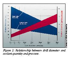
The quantity of coolant is just as important as the pressure. As the drill diameter increases, coolant quantity (in gpm) must increase and coolant pressure (in psi) must decrease proportionately (Figure 2). Since larger diameter drills produce more chips, proper coolant volume and pressure are needed to enhance the efficiency of chip evacuation. Most cutting tool manufacturers can provide recommendations on the proper combination of quantity and pressure for specific drilling applications.
Coolant lubricity is also a factor in drill life expectancy. Coolants with high oil content reduce the friction of the drill against the workpiece material and also help chips slide up and out of the hole more easily. Coolant choice depends on the material being drilled and the operation being performed. Deep-hole drilling in nonferrous materials such as high-temperature nickel-base alloys, for example, requires a coolant with a very high oil content to ensure efficient chip evacuation. Because it is very difficult to break chips in these materials, the added lubricity of the cutting fluid is needed to help the drill break chips more effectively. Most coolant manufacturers can recommend a coolant lubricity that best meets the requirements of a specific application.
Speed and Feeds
Selecting the proper speed and feed rate for a particular drilling application is critical to reducing drill wear and breakage. Speed and feed recommendations are always subject to specific job conditions, and manufacturersą suggestions are only estimates to give the operator an approximate starting point. What makes selecting the right parameters so difficult is that there is little margin for error. Speeds and feeds that are too high, as well as speeds and feeds that are too low, can cause drill breakage.
Although speeds and feed rates are determined by the type of material being drilled and the depth of the hole, there are two other important considerations to keep in mind‹toolholding and workholding. A frequent cause of drill breakage is a loose or poorly designed toolholder that imparts wobble to the drill. Even at slow speeds and feeds, wobble will quickly break a drill. There are many types of toolholding devices to choose from, but a hydraulic chuck is the most secure method of toolholding, because it generally has the least amount of runout. A very-close-tolerance collet chuck is the next best option, followed by an endmill-style holder.
The importance of using a high-quality toolholder and eliminating runout can be illustrated with an example using solid-carbide drills. Solid-carbide drills are built to take strong z-axis (thrust) force, but very little x- and y-axis force. A worn chuck or spindle can create runout of 0.0015" to 0.0020", and the forces produced by this wobble can break the drill. If the drill runs true (+ 0.0005"), however, speeds and feed rates can be set to the high side of the manufacturerąs recommendations without fear of drill breakage.
Workpiece clamping is also important. A loose workpiece also can produce side forces that can break a drill. If a drilling operation has been proceeding normally, and drills suddenly begin breaking, the first areas to check are the toolholder and the workpiece clamping.
Drill Selection
An operator can reduce the likelihood of drill breakage and, thereby, reduce the cost of holemaking operations by using the appropriate type of drill for the operation. There are four basic types of drills to choose from‹solid-carbide drills, drills with a carbide tip brazed into a steel shank, indexable-carbide-insert drills, and HSS drills.
For tight-tolerance, small-diameter holes, solid-carbide drills are the best choice. The stiffness of the carbide shank ensures a true-running drill, assuming the drill and workpiece are held securely.
However, carbide drills are expensive, and the cost of these drills rises with the amount of carbide in them. As hole diameters and depths increase, making an increase in drill size necessary as well, a better selection may be a brazed-carbide-tip drill. The steel shank of this type of drill may be more flexible than a solid-carbide drill, but the brazed-carbide-tip construction makes these drills more economical to use than solid-carbide drills.
Indexable-insert drills are a good choice for certain applications. Although tolerances are not as tight with indexable-insert drills, their solid-steel shank and positive cutting action generally allow higher feed rates than other types of drills, and they are more economical to use, because the inserts can be replaced. It costs much less in money and time to swap a new insert for an old one than to send a drill out for regrinding. The solid-steel shank also provides extra rigidity for good hole-diameter accuracy and resistance to breakage. What distinguishes the indexable-insert drill from other types is that specialized chipbreakers can be easily incorporated into the inserts to improve chip evacuation and, therefore, increase productivity.
HSS drills are the most economical to use. While they lack the rigidity to produce the same close-tolerance holes as carbide drills, they can handle a large chipload, making them a good choice for some deep-hole-drilling applications.
Drills are not the only choice for holemaking, however. Engineers have found that for hole diameters greater than 2", facemilling cutters work better than drills. Circular- and helical-interpolated milling cutters using button inserts can produce holes that are close to boring-bar quality in roundness, size, and finish and are not subject to the same stresses as drills. This is a very cost-effective way of making large-diameter holes, since this approach eliminates the need for an extensive inventory of large-diameter drills. A rule of thumb for selecting the proper facemilling cutter is that the cutter diameter should be no greater than the hole diameter and no smaller than 1/2 the hole diameter.
Among the many factors that influence drill breakage and premature wear, coolant delivery is the most critical, followed by selection of the proper speed and feed rate. However, other factors such as toolholding and workholding practices can have a direct impact on tool life, and selecting the correct type of drill for the specific application can also contribute to an overall reduction in breakage. It is important to remember that no two jobs are exactly alike, and no two machine tools are exactly alike. Knowing why drill breakage happens, combined with experience, can help machine tool operators control breakage problems and ultimately reduce the cost of holemaking operations.
About the Author
Jeff Fox is national sales manager for Widia North America, Cincinnati.
Related Glossary Terms
- alloys
alloys
Substances having metallic properties and being composed of two or more chemical elements of which at least one is a metal.
- burnishing
burnishing
Finishing method by means of compressing or cold-working the workpiece surface with carbide rollers called burnishing rolls or burnishers.
- centers
centers
Cone-shaped pins that support a workpiece by one or two ends during machining. The centers fit into holes drilled in the workpiece ends. Centers that turn with the workpiece are called “live” centers; those that do not are called “dead” centers.
- chuck
chuck
Workholding device that affixes to a mill, lathe or drill-press spindle. It holds a tool or workpiece by one end, allowing it to be rotated. May also be fitted to the machine table to hold a workpiece. Two or more adjustable jaws actually hold the tool or part. May be actuated manually, pneumatically, hydraulically or electrically. See collet.
- collet
collet
Flexible-sided device that secures a tool or workpiece. Similar in function to a chuck, but can accommodate only a narrow size range. Typically provides greater gripping force and precision than a chuck. See chuck.
- coolant
coolant
Fluid that reduces temperature buildup at the tool/workpiece interface during machining. Normally takes the form of a liquid such as soluble or chemical mixtures (semisynthetic, synthetic) but can be pressurized air or other gas. Because of water’s ability to absorb great quantities of heat, it is widely used as a coolant and vehicle for various cutting compounds, with the water-to-compound ratio varying with the machining task. See cutting fluid; semisynthetic cutting fluid; soluble-oil cutting fluid; synthetic cutting fluid.
- cutting fluid
cutting fluid
Liquid used to improve workpiece machinability, enhance tool life, flush out chips and machining debris, and cool the workpiece and tool. Three basic types are: straight oils; soluble oils, which emulsify in water; and synthetic fluids, which are water-based chemical solutions having no oil. See coolant; semisynthetic cutting fluid; soluble-oil cutting fluid; synthetic cutting fluid.
- depth-to-diameter ratio
depth-to-diameter ratio
Ratio of the depth of a hole compared to the diameter of the tool used to make the hole.
- facemilling
facemilling
Form of milling that produces a flat surface generally at right angles to the rotating axis of a cutter having teeth or inserts both on its periphery and on its end face.
- feed
feed
Rate of change of position of the tool as a whole, relative to the workpiece while cutting.
- gang cutting ( milling)
gang cutting ( milling)
Machining with several cutters mounted on a single arbor, generally for simultaneous cutting.
- high-speed steels ( HSS)
high-speed steels ( HSS)
Available in two major types: tungsten high-speed steels (designated by letter T having tungsten as the principal alloying element) and molybdenum high-speed steels (designated by letter M having molybdenum as the principal alloying element). The type T high-speed steels containing cobalt have higher wear resistance and greater red (hot) hardness, withstanding cutting temperature up to 1,100º F (590º C). The type T steels are used to fabricate metalcutting tools (milling cutters, drills, reamers and taps), woodworking tools, various types of punches and dies, ball and roller bearings. The type M steels are used for cutting tools and various types of dies.
- lubricity
lubricity
Measure of the relative efficiency with which a cutting fluid or lubricant reduces friction between surfaces.
- metalworking
metalworking
Any manufacturing process in which metal is processed or machined such that the workpiece is given a new shape. Broadly defined, the term includes processes such as design and layout, heat-treating, material handling and inspection.
- milling
milling
Machining operation in which metal or other material is removed by applying power to a rotating cutter. In vertical milling, the cutting tool is mounted vertically on the spindle. In horizontal milling, the cutting tool is mounted horizontally, either directly on the spindle or on an arbor. Horizontal milling is further broken down into conventional milling, where the cutter rotates opposite the direction of feed, or “up” into the workpiece; and climb milling, where the cutter rotates in the direction of feed, or “down” into the workpiece. Milling operations include plane or surface milling, endmilling, facemilling, angle milling, form milling and profiling.
- shank
shank
Main body of a tool; the portion of a drill or similar end-held tool that fits into a collet, chuck or similar mounting device.
- stiffness
stiffness
1. Ability of a material or part to resist elastic deflection. 2. The rate of stress with respect to strain; the greater the stress required to produce a given strain, the stiffer the material is said to be. See dynamic stiffness; static stiffness.
- tap
tap
Cylindrical tool that cuts internal threads and has flutes to remove chips and carry tapping fluid to the point of cut. Normally used on a drill press or tapping machine but also may be operated manually. See tapping.
- tapping
tapping
Machining operation in which a tap, with teeth on its periphery, cuts internal threads in a predrilled hole having a smaller diameter than the tap diameter. Threads are formed by a combined rotary and axial-relative motion between tap and workpiece. See tap.
- toolholder
toolholder
Secures a cutting tool during a machining operation. Basic types include block, cartridge, chuck, collet, fixed, modular, quick-change and rotating.
- web
web
On a rotating tool, the portion of the tool body that joins the lands. Web is thicker at the shank end, relative to the point end, providing maximum torsional strength.
- workhardening
workhardening
Tendency of all metals to become harder when they are machined or subjected to other stresses and strains. This trait is particularly pronounced in soft, low-carbon steel or alloys containing nickel and manganese—nonmagnetic stainless steel, high-manganese steel and the superalloys Inconel and Monel.