END USER: Ansco Machine Co., (330) 929-8181, www.ansco-machine.com
SOLUTION PROVIDER: DP Technology Corp., (800) 627-8479, www.espritcam.com
CHALLENGE: More efficiently program large mill-turn vertical turret lathes.
SOLUTION: CAM software that can program complex mill-turn parts using subprograms.
Ansco Machine Co. is a family-owned job shop specializing in milling and turning. Ansco primarily serves customers in the steel mill, energy, automation, fluid power, liquid natural gas, oil and gas, and offshore drilling industries.
Ansco, Cuyahoga Falls, Ohio, opened in 1991 with two Bridgeports and a handful of manual lathes and vertical turret lathes (VTLs). A few years later, the company acquired its first CNC machine, a 1979 Warner & Swasey 2SC, thrusting the company into the world of CAD/CAM software.
Ansco initially programmed with a simple 2D lathe package. Despite its simplicity, the software served the company well until Ansco began to expand and its needs became more complex. After outgrowing its original building and moving twice, Ansco now employs 50 people and has 14 CNC lathes, seven horizontal machining centers, five VTLs and four vertical machining centers in its 38,000-sq.-ft. facility.
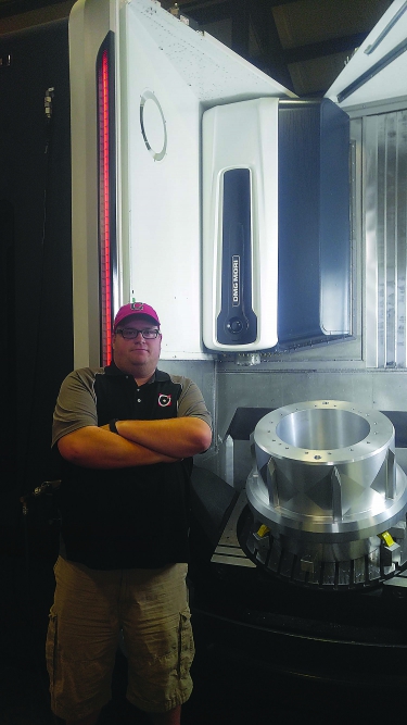
Ansco Machine Applications Engineer Dave Sterling stands next to a suction manifold and the company’s DMG Mori DMU 65 monoBLOCK. All images courtesy of Ansco Machine.
As Ansco’s projects grew larger and more complicated, the company knew that it needed a better way to program its large mill-turn VTL machines. “We were having to do manual code edits on every feature we made,” said Dave Sterling, applications engineer and the son of Ansco owner Mike Sterling. “I used to write main and subprograms by hand in order to use the machines’ polar interpolation feature. This was OK for straightforward parts, but having to create an individual program with hand edits for more-complicated parts consumed an excessive amount of time.”
Ansco began the search for a CAM system that would allow its applications engineers to be more flexible and efficient—a process that took a few years. On several occasions, Dave Sterling and his colleagues met with Dan Frayssinet—president of DP Technology Corp., Camarillo, Calif., which develops ESPRIT CAM software—and members of the ESPRIT sales team. They discussed the mill-turn issues that Ansco’s simple software couldn’t handle. In the end, it was ESPRIT software’s ability to program complex mill-turn parts using subprograms that turned Ansco into a customer. Its initial purchase was for three seats.
Then, Ansco received an emergency inquiry from a customer in the liquid natural gas industry. The customer needed an order of fan-type inducers within a week. Ansco had made a few similar parts in the past using one of five Makino HMCs, but the process was painstaking. Sterling would machine one side of the part, make a nest for it, then cut the back. This method worked well enough but wasn’t ideal.
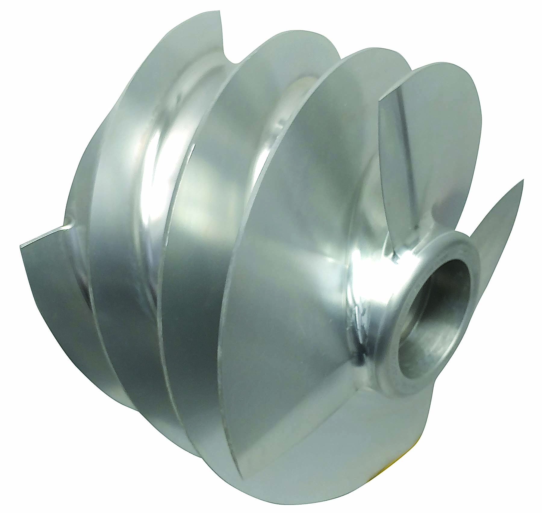
For this fan-type inducer, Ansco Machine used ESPRIT CAM software to program the part on a DMG Mori DMU 65 monoBLOCK machine.
The new inducers could be programmed on an HMC. However, the parts’ complexity would require knowledge of 5-axis machining, which Sterling didn’t have. He called ESPRIT. Two days later, he was on a plane to Charlotte, N.C., to get one-on-one training that would enable him to do 5-axis programming on Ansco’s 4-axis Makino machine. Ansco completed the order in time and went on to use the same method for a number of other parts.
Later, Ansco needed to undercut a more complex inducer and realized that a 4-axis machine wouldn’t do the trick. The company considered contracting the work to another shop but ultimately invested in a DMG Mori DMU 65 mono-BLOCK to complete the job.
“ESPRIT was key in my success at 5-axis milling,” Sterling said. “Right out of the box, I had a solid model of the machine, a predefined template and a factory-tested post-processor. The installation engineer was skeptical at first and said, ‘No post is perfect right out of the box.’ But the more parts we machined, the more we realized that the ESPRIT post really was just that good.”
Sterling added that with so many variables in programming a new machine, having a reliable post-processor is important. The most recent 5-axis program he ran had 5.5 million lines of code. “I couldn’t make sense of it even if I wanted to,” he said. “But having a reliable simulation and a post I could count on let me focus on workholding, tooling and the actual machining of the part. If it happens on the screen in simulation, it happens on the machine. That’s huge for us.”
Having a reliable post-processor, accurate simulations and attentive customer service—not to mention the ability to easily write millions of lines of code—lowers Sterling’s stress level. It also lowers Ansco’s engineering costs and the time spent on projects.
Contact Details
Related Glossary Terms
- centers
centers
Cone-shaped pins that support a workpiece by one or two ends during machining. The centers fit into holes drilled in the workpiece ends. Centers that turn with the workpiece are called “live” centers; those that do not are called “dead” centers.
- computer numerical control ( CNC)
computer numerical control ( CNC)
Microprocessor-based controller dedicated to a machine tool that permits the creation or modification of parts. Programmed numerical control activates the machine’s servos and spindle drives and controls the various machining operations. See DNC, direct numerical control; NC, numerical control.
- computer-aided manufacturing ( CAM)
computer-aided manufacturing ( CAM)
Use of computers to control machining and manufacturing processes.
- gang cutting ( milling)
gang cutting ( milling)
Machining with several cutters mounted on a single arbor, generally for simultaneous cutting.
- interpolation
interpolation
Process of generating a sufficient number of positioning commands for the servomotors driving the machine tool so the path of the tool closely approximates the ideal path. See CNC, computer numerical control; NC, numerical control.
- lathe
lathe
Turning machine capable of sawing, milling, grinding, gear-cutting, drilling, reaming, boring, threading, facing, chamfering, grooving, knurling, spinning, parting, necking, taper-cutting, and cam- and eccentric-cutting, as well as step- and straight-turning. Comes in a variety of forms, ranging from manual to semiautomatic to fully automatic, with major types being engine lathes, turning and contouring lathes, turret lathes and numerical-control lathes. The engine lathe consists of a headstock and spindle, tailstock, bed, carriage (complete with apron) and cross slides. Features include gear- (speed) and feed-selector levers, toolpost, compound rest, lead screw and reversing lead screw, threading dial and rapid-traverse lever. Special lathe types include through-the-spindle, camshaft and crankshaft, brake drum and rotor, spinning and gun-barrel machines. Toolroom and bench lathes are used for precision work; the former for tool-and-die work and similar tasks, the latter for small workpieces (instruments, watches), normally without a power feed. Models are typically designated according to their “swing,” or the largest-diameter workpiece that can be rotated; bed length, or the distance between centers; and horsepower generated. See turning machine.
- milling
milling
Machining operation in which metal or other material is removed by applying power to a rotating cutter. In vertical milling, the cutting tool is mounted vertically on the spindle. In horizontal milling, the cutting tool is mounted horizontally, either directly on the spindle or on an arbor. Horizontal milling is further broken down into conventional milling, where the cutter rotates opposite the direction of feed, or “up” into the workpiece; and climb milling, where the cutter rotates in the direction of feed, or “down” into the workpiece. Milling operations include plane or surface milling, endmilling, facemilling, angle milling, form milling and profiling.
- milling machine ( mill)
milling machine ( mill)
Runs endmills and arbor-mounted milling cutters. Features include a head with a spindle that drives the cutters; a column, knee and table that provide motion in the three Cartesian axes; and a base that supports the components and houses the cutting-fluid pump and reservoir. The work is mounted on the table and fed into the rotating cutter or endmill to accomplish the milling steps; vertical milling machines also feed endmills into the work by means of a spindle-mounted quill. Models range from small manual machines to big bed-type and duplex mills. All take one of three basic forms: vertical, horizontal or convertible horizontal/vertical. Vertical machines may be knee-type (the table is mounted on a knee that can be elevated) or bed-type (the table is securely supported and only moves horizontally). In general, horizontal machines are bigger and more powerful, while vertical machines are lighter but more versatile and easier to set up and operate.
- solid model
solid model
3-D model created using “building blocks.” This is the most accurate way of representing real-world objects in CAD.
- turning
turning
Workpiece is held in a chuck, mounted on a face plate or secured between centers and rotated while a cutting tool, normally a single-point tool, is fed into it along its periphery or across its end or face. Takes the form of straight turning (cutting along the periphery of the workpiece); taper turning (creating a taper); step turning (turning different-size diameters on the same work); chamfering (beveling an edge or shoulder); facing (cutting on an end); turning threads (usually external but can be internal); roughing (high-volume metal removal); and finishing (final light cuts). Performed on lathes, turning centers, chucking machines, automatic screw machines and similar machines.
- undercut
undercut
In numerical-control applications, a cut shorter than the programmed cut resulting after a command change in direction. Also a condition in generated gear teeth when any part of the fillet curve lies inside of a line drawn tangent to the working profile at its point of juncture with the fillet. Undercut may be deliberately introduced to facilitate finishing operations, as in preshaving.
Author
News items authored by Cutting Tool Engineering have been written or edited by the editors of Cutting Tool Engineering magazine. The reports represent material submitted to CTE by outside authors, and edited by CTE editors for style and accuracy.
END USER: Ansco Machine Co., (330) 929-8181, www.ansco-machine.com
SOLUTION PROVIDER: DP Technology Corp., (800) 627-8479, www.espritcam.com
CHALLENGE: More efficiently program large mill-turn vertical turret lathes.
SOLUTION: CAM software that can program complex mill-turn parts using subprograms.