Specialized tools help deburr cross-holes
Specialized tools help deburr cross-holes
Automated deburring makes the process more efficient, giving the end product a more consistent finish from part to part.
Deburring drilled holes is essential to the manufacturing process. Burrs that aren't cleaned up can cause part failure by breaking off and clogging or damaging a part or an assembly or by cutting a wire or an O-ring that's passed through a bore. But cross-holes, where two or more holes intersect, are hard to reach and often require deburring by hand.
When cross-hole deburring, challenges are commonly encountered in applications with sloped or uneven surfaces, wide penetration angles, multiple intersecting bores, 1-1 ratio cross-bores and microscale bores. The burrs that develop in these situations frequently can't be easily removed with standard deburring tools on a CNC machine.
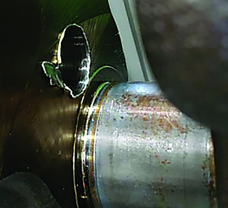
This manufacturer needed to deburr its V-8 crankshafts that consist of a main bore that breaks out into seven different surfaces, some of which are angled/irregular cast surfaces. Image courtesy of Heule Tool
"Cross-hole deburring is an issue for our customers because typically they have to take the part off the machine and remove that burr by hand, which takes a lot of time and actually can cause physical stress for a machinist to do the tedious labor of deburring," said Lynn Bissell, sales and marketing coordinator at Heule Tool Corp., Loveland, Ohio. "Automated deburring with a tool in the CNC machine provides a solution that makes the process more efficient and gives the end product a more consistent finish from part to part."
Complex Shapes
Drilling a hole through a flat plate of metal generates a flat, 2D circle. "So going in and deburring it on the backside is no different than deburring that same edge on the outside, because there's no complex shapes," said Stan Kroll, partner and general manager at J.W. Done Corp., Hayward, California.
But in the case of cross-holes, when burrs occur deep inside a part, things become tricky.
"Whenever you have people using abrasive stones or carbide rotary burs by hand, it's got to go in very carefully without scratching up the wall or without moving too far down the hole and scratching up any other features beyond the edge," Kroll said. "You try to carefully and selectively follow just the edge where the burr is, and that's not so easy to do when you can't see inside very easily."
Automating this task on a CNC machine requires complex programming to follow the 3D elliptical shape created when two round holes intersect, which is sometimes called a potato chip or a saddle shape.
Saddle Burrs
On saddle-shaped cross-holes, many tools designed to deburr flat holes will cut high on the high spots and cut low or do nothing on the low spots, according to Bill Hargrove, national sales manager at Heule Tool. "This leaves bigger edge breaks on the high spots and smaller edge breaks on the low ones, or it may not deburr completely all the way around the hole."
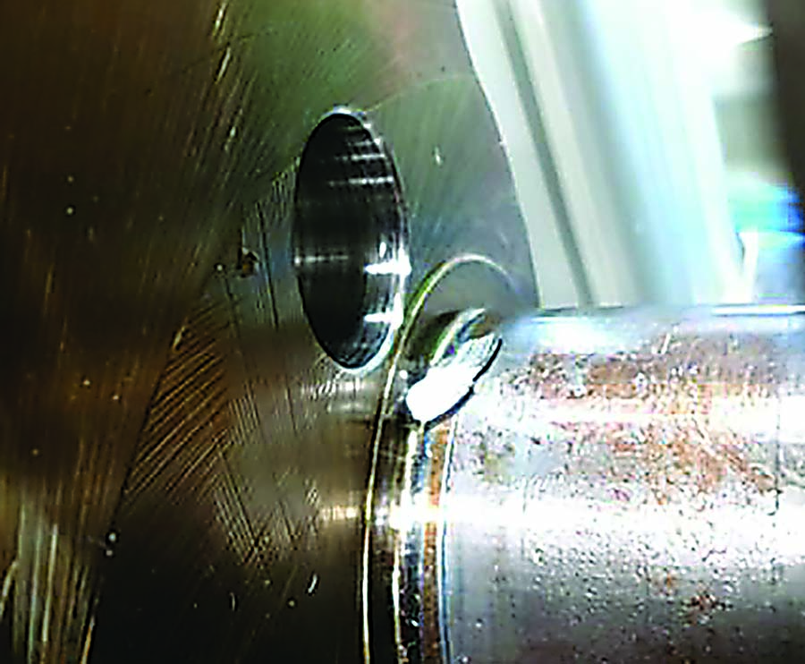
In some precision applications, the uneven size of the edge break is a concern. Heule developed its line of Cofa deburring tools to produce a consistent edge break throughout the surface of a saddle-shaped cross-hole. The carbide cutting blade is controlled by a simple spring that allows it to pass through a bore without cutting or damaging the bore's surface. Once the blade exits to the interior of the cross-hole, it opens to interact with burrs wherever it comes into contact with metal, pivoting to follow the contour of the hole's surface. This way, the tool can remove all burrs while creating an even-tapered corner break.
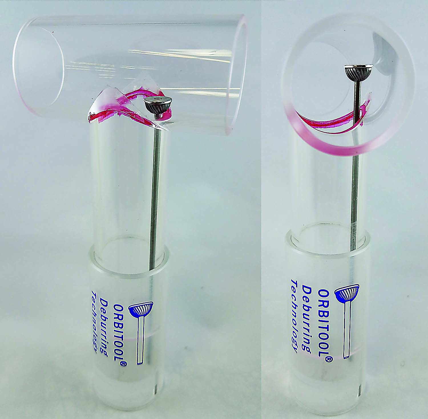
The Orbitool by J.W. Done is used just like any cutting tool found on a lathe turret or tool magazine of a milling machine. The operation removes burrs from the intersection of cross-holes and can be tailored to leave a minimally broken edge or a blended radius. Image courtesy of J.W. Done
"It's a unique tool that is simple to use," Hargrove said. "It's just straight through the center of the hole and straight back out through the center of the hole. It does not need a complex program to follow the contour, because the blade does all of the work."
Ratio in Balance
Another solution to the potato chip problem is J.W. Done's Orbitool. Kroll said it was developed to remove burrs from the intersections of cross-holes of nearly or exactly the same size—sometimes called 1-1 cross-holes—such as those seen at the 90° elbow of T-pipes common in fittings and manifolds.
As the diameters of the two holes reach identical size, the potato chip shape expands until the intersection reaches halfway up the sides of both holes. This configuration is typical yet extremely difficult or even impossible for many deburring tools.
"A lot of traditional tools always had a hole ratio limitation," Kroll said. "They could do cross-holes but only up to a certain cross-hole size in relation to the bore."
The Orbitool looks like a traditional carbide rotary bur, which is essentially a ball-shaped milling cutter mounted on a rigid shaft.
The difference is the combination of a flexible shaft and a protective metal ring, or disc, which encircles the end of the tool. Kroll said the ring makes it physically impossible for the carbide cutting tool to touch anything but the actual edge of the holes' intersection, thereby protecting the rest of the part from any stray damage.
"Then the most important thing about our tool is what we call a helical interpolation, which in simple terms is a thread spiral," Kroll said. "Just as if you were programming a standard thread milling routine with the CAM cycle in a CNC machine, you program the tool to interpolate and gradually feed down the hole towards the edge, essentially tracing the ID of that hole. It'll constantly flex and adjust and move out of the way if it encounters anything that should be protected. But during that process, it's going to remove the burrs from all of those edges."
This flexibility is helpful for deburring parts with uneven or offset surfaces.
Sometimes holes exit into castings and forgings with irregular surfaces that aren't necessarily predictable, and end users can't program a tool to know exactly where that edge is going to be, Kroll noted. "That's where something like the Orbitool becomes very handy because we're not programming it to actually find the edge, and in fact we never tell the tool where the edge is located."
Brush Them Away
Another method for deburring these difficult shapes on a CNC without elaborate programming is to use deburring brushes. These tools self-center and self-align to a bore so elaborate, rigid setups are not required. The brushes can handle angled cross sections, irregular surfaces and multiple cross-holes in a cylindrical bore. Contingent on the tool, it may be usable on a CNC machine, as well as off-machine with a hand drill or drill press.
"We have a few different lines for deburring cross-holes, depending on the thickness of the burrs, the base material, the size of the hole and the surface finish requirements," said Elysha Cole, applications engineer at Brush Research Manufacturing Co. Inc., Los Angeles. "For the larger holes—4mm and up—we offer the Flex-Hone Tool, which is a flexible nylon filament rotary brush with abrasive globules on the end of each filament. The Flex-Hone moves into the bore in an oversized state. When it exits the bore to the ID, the globules pop out into the cross-hole a little bit, which allows them to get those burrs."
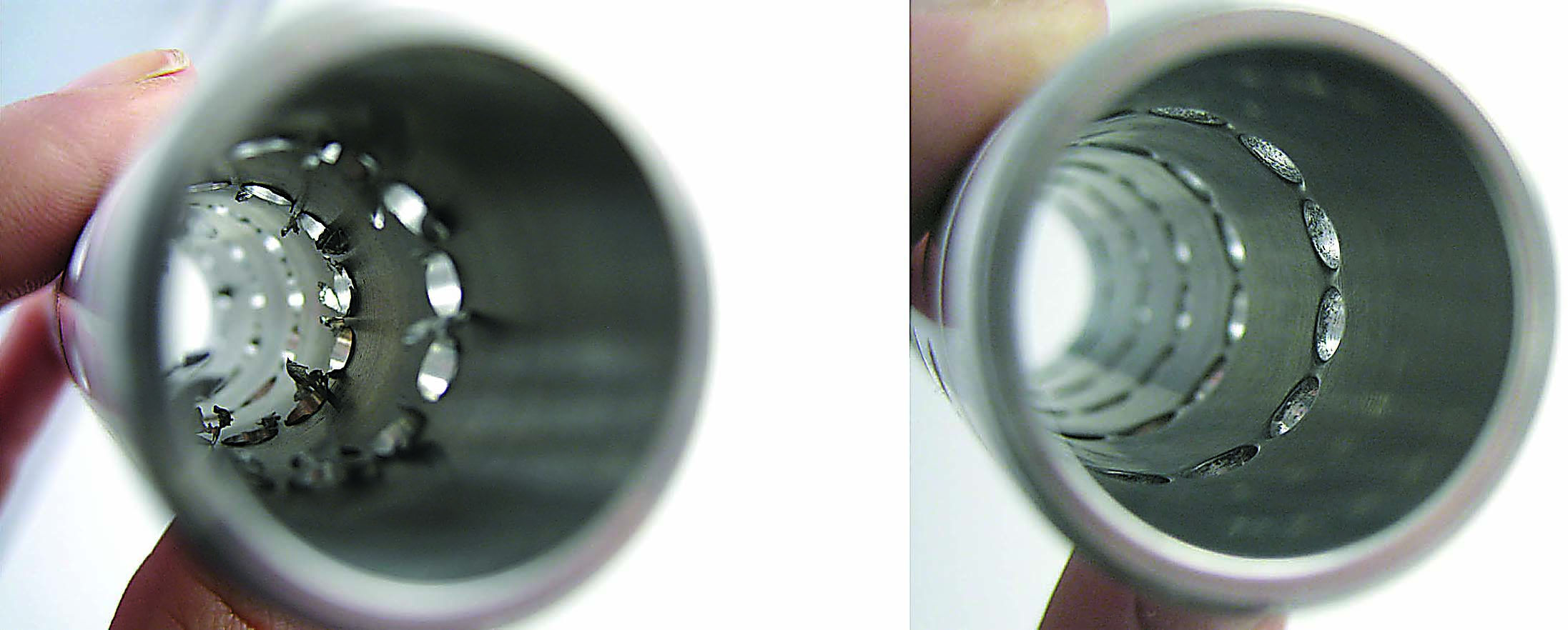
Before and after deburring multiple cross-holes in a bore using the Flex-Hone Tool. Image courtesy of Brush Research Manufacturing
Brushes are especially good at deburring nonstandard shapes and surfaces.
"Because the tool is flexible, angles are not such a big deal," Cole said. "In the case where a cross-hole breaks into a bore at an angle, as long as the brush can go through the cylindrical main ID, it will deburr the sharp edges and produce a slight radius on that elliptical hole."
In some cases, a brush may need additional maneuvering.
A brush is most effective when it moves perpendicular to the edge being deburred rather than parallel, said Rick Sawyer, general manager of Automated Deburring Solutions, a subsidiary of Weiler Abrasives Group, Cresco, Pennsylvania. "A bore that comes in at an angle to the main bore creates an oval opening. So as I rotate the brush down through it, I get the sides of the oval very well, but I don't get the top and the bottom as well unless I also oscillate the brush back and forth."
Abrasive brushes can be used for a range of small holes as well depending on the hole and burr.
"Above an inch in bore size, I have a lot of options—for example, Bore-Rx brushes, which have nylon abrasive filaments with ceramic abrasive grains coextruded through them," Sawyer said. "With larger brush diameters, I get a lot of filament, which means I get a lot of cutters as every grain is actually a minicutter. But once you get below an inch, now I must start going down in the filament's diameters, which limits the grain size it can carry."
Sawyer said brushes ¼" and smaller can support fine-grain sizes of only 500 or 1,000 grit and can't remove a heavy burr.
"All it can do is polish," he added. "If the burr is loose, the brush can go in there and push it out. But it can't detach it, because it just doesn't have enough horsepower, so to speak."
Using coolant impacts a brush's deburring efficiency.
"If the brush is dry, such as in the case of a robotic cell, I can only bring it up to about 2,000 surface feet per minute because the abrasive grain generates heat," Sawyer said. "Meaning at higher speeds, the nylon filament itself may start to melt or transfer onto the part. If we have coolant, the abrasive media will leave a nicer finish, and it also allows us to run the brush more aggressively by increasing rpm or having a larger depth of interference."
Sawyer said these types of products tend to work better with water-soluble coolant rather than oil-based coolant because the former doesn't cause buildup onto the abrasive grain.
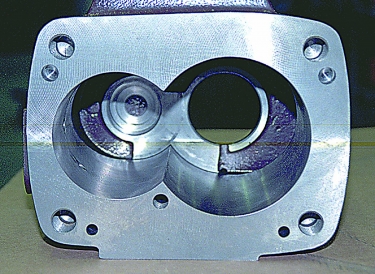
Screw compressor housings have adjoining bores, which create a sharp interior angle that must be deburred to ensure successful operation. Small Nylox wheel brushes are suitable for this application. Image courtesy of Weiler Abrasives Group
"When I look at a burr, it's all about root thickness," Sawyer said. "How well attached is it? How much energy will it take to remove it? In some cases, it's too well attached and you need a deburring tool or stone to cut it off." When this happens, a brush is often still required to remove the secondary burr generated by the hard tool or stone.
In contrast to the cutting action of a carbide bur, a brush performs a filing action. This is akin to the way that a nail clipper cuts a nail and a file merely smooths edges. But in cases where a brush can do the job, a brush offers several benefits.
"Our brushes are not going to remove material from your part, change the geometry or make the bore bigger," Cole said. "So if you have tight tolerances, for example, in aerospace applications, we can remove the burrs without removing metal."
The beauty of using a cross-hole deburring brush, Cole said, is that it potentially can perform two functions in one step—deburring and surface finishing—saving time and space on the tool magazine.
"You might not get the right finish with a carbide cutting bur, but our tools can do both," Cole said.
Supply Chain Benefits
The benefits of moving the deburring process to a CNC and applying specialized tools ascend the supply chain.
"With deburring tools like the Cofa, the manufacturer is able to produce parts faster and meet their production demands," Bissell said. "So they save money, and they also make the OEM customers that are buying the parts happy. But when you go up another level to where the parts are assembled to create products, those also can be
produced faster and with higher quality."
Ultimately, this increasing efficiency enables companies to meet consumer demand, Bissell said.
"For example, the increasing demand for air travel is creating a huge backlog in the aerospace industry as they're trying to meet that demand," Bissell said. "On that level, these tools are important because companies need to produce planes faster to get the project going and out the door."