Single-Pass Bore Finishing: General Industry Coverage
Superabrasive bore finishing can achieve results in one pass that rival the finishes produced in several passes by other bore sizing operations.
As an alternative to honing, single-pass superabrasive bore finishing is proving itself to be both cost-effective and versatile.
Throughout the 1990s, an increasing number of manufacturers have been meeting their hole-finishing needs with the single-pass superabrasive process. These users believe the process’s advantages over other bore-sizing operations such as honing give them a competitive edge. They have found that with single-pass superabrasive bore finishing they can achieve:
- Size control as good as 0.001mm in production.
- Bore geometry as good as 0.0005mm in production.
- Surface finish to better than 0.1µm Ra in most materials.
- Shorter cycle times.
- Quality bores with less skilled operators.
- Predictable, consistent results that lend themselves to statistical process control.
- Extremely long tool life.
- Lower overall cost per finished piece.
Many of the improvements to the single-pass process were developed in the R&D department of Engis Corp., Wheeling, IL. These advancements include proprietary designs relating to the diamond tool; bearing-mounted fixturing that allows the workpiece to float for perfect alignment with the least amount of force; machine tool functions such as peck feed that allow the diamond tool to travel a controlled distance in the bore, withdraw, and repeat throughout the part; precise slide positioning for blind bores; precise table positioning for achieving bore-to-datum concentricity; spring-loaded tooling for crash protection; optidirectional spindles that reverse direction every other cycle for extended tool life and improved bore geometry; various water-base coolants for alternatives to honing oil; and patented outer-diameter finishing products.
With these advancements, manufacturers can bore finish nearly any hole. The single-pass process can produce bores to spec in gummy materials such as aluminum and bronze, abrasive materials such as carbon and ceramics, easy-to-machine materials such as cast iron and powdered metal, and high-temperature alloys and hardened bearing steels.
Process Mechanics
The single-pass process is actually quite simple. The work is typically done by a preset, barrel-shaped tool coated with diamond or cubic-boron-nitride pArticles. The front portion of the single-pass tool is designed with an adequate amount of taper to allow the tool to enter the existing bore. Once the tool has entered the bore, a specific amount of material is removed along the remaining length of the tool.
The end user passes the tool once through the bore while either the tool, the part, or both are rotating. This is in contrast to conventional honing, in which, simultaneously on the same tool, the spindle rotates, the spindle or part moves back and forth axially, and the abrasive is fed out radially (Figure 1).
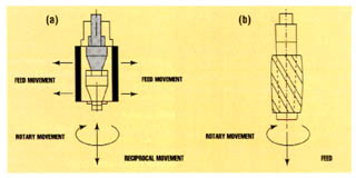
Figure 1: While a conventional honing tool must maintain bore size while moving in several directions at the same time (a), the single-pass toll achieves the same results by rotating and plunging into the hole only once (b). (Click for larger images)With the single-pass process, thousands of superabrasive pArticles around the full periphery of the tool gradually remove the material. With the cutting forces so widely distributed, heat and stress levels are kept to a minimum. This, combined with the float that allows the tool to follow the centerline of the existing bore exactly, enables excellent control of the part’s geometrical bore quality. This is in contrast to conventional honing, which also uses float to follow the centerline of the existing bore. In the case of honing, however, the need to expand and contract the cutting surfaces each cycle and the continual reciprocating motion through the bore have a negative effect on size control and overall bore geometry.
A single-pass tool controls bore size better than a hone will, because its cutting surfaces do not have to expand and contract during each cycle and the superabrasive wears so slowly. In fact, tool wear is so minimal that a user can finish the bores on many thousands of parts without producing any measurable difference in bore size.
However, for the single-pass superabrasive process to meet its potential, the equipment must be carefully selected. End users should seek the advice of the tooling supplier as they plan an application. A good supplier will review the proposed application and recommend the proper machine tool, fixturing, coolant, automation package, and filtration. The supplier also can design and produce a tool using the appropriate superabrasive, flute design, taper, length, and mandrel.
Stock Removal vs. Surface Finish
The amount of stock a single-pass superabrasive tool can remove and the surface finish it can produce are directly related to the size of its superabrasive pArticles. For example, a 100-grit tool can generally remove up to 0.075mm in a gray-cast-iron part and achieve a 1.5µm Ra surface finish. A 400-grit tool in the same material can produce a much finer finish, but it will be able to remove, at most, 0.025mm of stock.
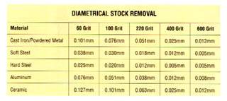
Table 1: the approximate amount of stock removal possible with single-pass tools of various grits. These numbers are for reference only, part shape and length can affect the tool’s stock-removal capabilities. Coarser grits are available for maximum removal. (Click for larger images)
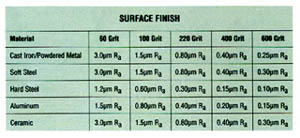
Table 2: The approximate surface finish achievable with sngle-pass tools of various grits. These numbers are for reference only, all are dependent on particular material specifications. Finer grits may be available for even lower surface finishes. (Click for larger images)The same principle holds true when finishing other materials (Tables 1 and 2). For example, in hardened steel a 100-grit tool may be able to remove 0.020mm of material and achieve a 0.60µm Ra finish. A 400-grit tool in the same material can produce a surface finish as low as 0.15 Ra, but it will be held to a much lower removal rate. Because many applications require both a high removal rate and a fine surface finish, end users frequently finish bores with a series of preset, single-pass tools. This is called a multitool operation.
To perform a multitool peration, the user sets each tool to remove its hare of the total material. As the part is passed from tool to tool, material is removed from the bore in ever-diminishing amounts to bring it to size. To accomplish this, the part is first machined with coarse-grit tools for maximum material removal and then fine-grit tools to produce the desired surface finish.
Applications that call for low stock removal or less precision can be completed with only one tool. Almost any type of toolroom machine can be used to drive the tool, including a honing machine, a drill press, a milling machine, a lathe, or a machining center. The end user must remember, however, that whatever machine is used, either the tool or the part must be mounted in a way that allows it to float.
For multitool operations, there is a range of state-of-the-art bore-finishing systems specifically designed to take advantage of the unique benefits of the single-pass process. These systems usually are equipped with a rotary index table so that the part-handling, roughing, and finishing operations can be performed simultaneously. The systems can be fitted with a specified number of spindles, as well as motors of various horsepowers, CNC controllers, different automation and fixture packages, gages, auxiliary stations, and columns.
Success in the Field
As the use of single-pass superabrasive bore finishing has grown, shops have found the process useful for a variety of applications. A typical job might involve finishing bores in hardened steel using a multitool setup. This is how one manufacturer used single-pass superabrasive bore finishing to machine hardened 12-L-14 steel valves. Because the tolerance for these parts was relatively open and the stock-removal requirements were minimal, the manufacturer was able to achieve very high production rates.
Using a 4-spindle bore-finishing machine with tools mounted in floating holders, the manufacturer removed a maximum of 0.012mm of material from the 25mm bores. The finished bores were specified to measure 6.350mm/6.356mm and have a roundness of 0.0030mm, a straightness of 0.0030mm, and a finish of 0.40µm Ra. Using the single-pass process, the manufacturer achieved a 6.352mm/6.354mm bore measurement with a roundness of 0.0015mm, a straightness of 0.0010mm, and a finish of 0.25µm Ra. With this setup, the manufacturer was able to finish 1600 parts per hour per machine. Each tool finished 50,000 parts before wearing out.
Increasingly, global competition and market demands are forcing manufacturers to machine parts to extremely tight tolerances. In the case of bore geometrical tolerances, more and more applications now require better than 0.0005mm in production. Manufacturers have found that single-pass bore finishing can help them achieve this level of precision cost effectively.
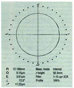
Figure 2: As this roundness measurement of a finished bore shows, the single-pass process can hold extremely tight tolerances. (Click for larger images)One manufacturer was able to finish 60 fuel-injection barrels per hour per machine while maintaining tolerances even better than specified using a single-pass system. The 39mm bores were in steel hardened to RC 62. Using an 8-spindle bore-finishing machine and part fixtures with float built into them, the manufacturer removed 0.100mm from each bore. The bore size the system produced was 11.005mm/11.007mm, which was better than the specified 11.000mm/11.015mm. The tolerance on roundness for the bores was specified to be 0.0005mm. The single-pass process was able to hold a 0.0003mm tolerance (Figure 2). Straightness, specified at 0.0006mm tolerance, was held to 0.0002mm, and the 0.4µm Rz finish that was achieved was 0.2µm better than the 0.6µm Rz specified. Tool life was estimated to be 20,000 to 50,000 parts per tool.
Manufacturers have found they can also use the single-pass process to finish blind bores. A bore is considered blind whenever there is a clearance restriction at one end that will not allow much of the finishing tool to pass through. In some cases, workpieces have been finished successfully with bore clearances under 2.5mm. (The clearance is the distance from the lowest part of the bore to be finished to a restriction.)
For the success of a blind-bore application, the diamond tooling, fixturing, and machine tool design must be chosen with care. One manufacturer was able to finish 100mm bores with a 2.5mm restriction in cast-iron
turbochargers using the single-pass process. This work was performed on an 8-spindle machine using a floating toolholder. A maximum of 0.127mm was removed from each bore, and the size, roundness, straightness, and finish of the bores were all better than specified. The manufacturer was able to finish 180 parts per hour per machine and finish 80,000 parts with each tool.
Using special fixtures that allowed operators to run a family of parts without changeover, another manufacturer was able to finish 40mm bores with 8mm of clearance in cast-iron pumps. The manufacturer’s 6-spindle machines removed a maximum of 0.050mm from 157 parts per hour, and each tool could finish 100,000 parts before wearing out. Again, size, roundness, straightness, and finish were all better than specified.
In some cases, a single tool is able to remove sufficient stock while achieving the specified finish. For example, one manufacturer was able to finish cast-iron tappet bores using a setup with a single tool mounted on a transfer system. The tool was used to remove a maximum of 0.075mm from the 44mm bores. The process was able to achieve a 1.5µm Ra finish, which was 0.5µm better than the finish that was specified. Bore size, roundness, and straightness were all also better than specified.
Meeting New Needs
Once manufacturers find a successful process, they begin experimenting to see how they might adapt the process to meet other needs. Recently, manufacturers have begun using the single-pass process to create cross-hatch or sine-curve scratch patterns on finished bores. Automotive engineers believe these patterns help retain oil in an engine’s cylinder bores. Manufacturers produce this pattern by feeding a proprietary designed single-pass superabrasive tool through a bore at a feed rate that is higher than normal. This removes only a portion of the part’s material. Then the tool is reciprocated through the bore a number of times at a spindle speed and feed rate that are set to produce the desired cross-hatch angle. Adding a controlled pecking motion to the process produces a sine-curve pattern.
With this method, manufacturers have been able to produce the desired pattern on the bore surface while still enjoying the benefits of the single-pass process. The process allows the manufacturer to finish long uninterrupted bores even in gummy materials by breaking up the chip, thereby permitting a fresh supply of lubricating fluid to enter the work area. This method also allows manufacturers to produce patterns even in situations, such as the finishing of thin-walled components, where cutting stresses must be held to a minimum.
In the automotive industry, manufacturers are attempting to perform single-pass superabrasive bore finishing with water-base coolants as part of their effort to eliminate oil coolants wherever possible in the manufacturing of engine components. One manufacturer, using specially developed single-pass superabrasive tools and a water-base coolant, was able to finish bronze bushings in connecting rods to better than 0.5µm Ra at high production rates. The manufacturer was removing 0.037mm from the 25mm bores using a 2-spindle transfer system and a floating fixture for the part. The production rate was 360 parts per hour per machine while maintaining size, straightness, and roundness at levels better than specified. Tool life was up to 1 million parts per tool.
In a more radical departure from standard single-pass bore finishing, one manufacturer adapted the process to move the existing centerline of a bore, while also establishing size. In the single-pass process, the diamond tool typically follows the bore’s existing centerline. But with specially designed diamond tools, an extremely accurate machine tool, and specially designed rotating fixtures, single-pass techniques can be used to make the centerline concentric to a datum or feature on the part. Using these modifications on a 4-spindle bore-finishing machine, the manufacturer moved the centerlines and finished the 25mm bores of a bearing housing’s carbon bushings. The process was able to achieve better than specified size, roundness, straightness, and finish. In addition, the manufacturer was able to hold a 2 Cpk and improve bore-to-datum concentricity to <0.050mm from 0.100mm.
Since a great number of hydraulic valves are currently being finished with the single-pass process, it seemed only natural that manufacturers would develop a similar process to finish the angled valve-seating areas. This has been accomplished by using one or more spring-loaded diamond seating tools to make a controlled pass and dwell on the part’s surface in a self-centering manner. Using this technique, one manufacturer was able to control the surface finish, achieve roundness as good as 0.001mm, and produce parts with low leak rates. The material was 1215 heat-treated steel. A 4-spindle machine was used to remove 0.012mm from the valve seat’s 90° angle. The system finished 626 parts per hour, and tool life was 15,000 parts per tool.
The development of the single-pass superabrasive bore-finishing process has come a long way since its introduction. Applications that were once thought impossible are now being handled routinely. Ongoing research and development programs will continue to expand the capabilities of this process. Because of this, it is almost assured that as the next millennium approaches, the single-pass superabrasive bore-finishing process will continue to grow in popularity as a means for manufacturing components to an ever higher degree of quality at a low overall cost per piece.
About the Author
Robert Marvin is product manager for bore-finishing systems, Engis Corp., Wheeling, IL.


MFGAxis Discussion