Making parts for hydraulic fracturing equipment presents opportunities but requires the right tools.
As the U.S. strives to become less dependent on foreign energy sources, energy producers are increasingly employing hydraulic fracturing, or “fracking,” to drill shale deposits and extract natural gas and some oil. That booming market requires a range of parts from shops around the country.

Learn more about making parts for hydraulic fracturing equipment
For more information, view a video presentation from MAG about programmable boring bars and read a short article about the origin and use of the word “fracking” on www.ctemag.com by clicking here.
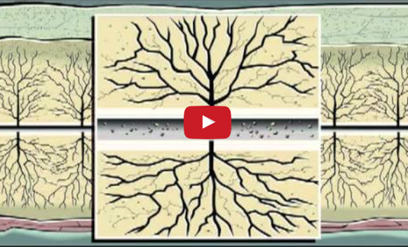
The fracking process involves vertically drilling a well thousands of feet into the ground and then horizontally drilling into the shale. There, a wire equipped with explosive charges perforates the well casing to create fissures in the fine-grain shale. Millions of gallons of a water, sand and chemical mixture are then pumped, at high pressure, into wells to expand the fissures and enable gas to pass through them. As the mixture is pumped out of the well, the gas follows the pipeline to the wellhead on the surface.
In April 2011, the U.S. Energy Information Administration estimated that the U.S. had 862 trillion cubic feet of technically recoverable shale gas during 2009, stated PricewaterhouseCoopers LLP in its report, “Shale Gas: A renaissance in US manufacturing?” The report noted that the Marcellus basin, located primarily in the mid-Atlantic, is considered the largest U.S. shale deposit with 410 tcf of technically recoverable natural gas per EIA estimates. However, a more recent assessment from the United States Geological Survey estimates 84 tcf of technically recoverable gas in this formation, underscoring the uncertainty around these figures, according to PwC, a provider of consulting and other services.
In addition to the Marcellus basin, shale deposits are being drilled in many states, including Michigan, Texas, Oklahoma, Colorado, Arkansas and Alabama.
In the report, Jay Timmons, president and CEO of the National Association of Manufacturers, stated: “More and more Americans are beginning to recognize the enormous potential of shale gas. The impact of increased shale gas development will ripple through our economy, with manufacturers, in particular, seeing great benefits. Shale gas development has the potential to boost manufacturing employment by one million jobs by the middle of the next decade.”
Machining Pump Parts
One manufacturer serving the fracking sector that has already added jobs is Weir SPM, Ft. Worth, Texas, which makes pumps and flow controls for the drilling and well-service/stimulation markets and provides aftermarket recertification and repair services. Since the end of 2009, the company has added about 1,000 employees globally, more than doubling its workforce, noted Matt Treida, product manager – flow products. “We’ve seen tremendous growth in the last 2 years—more than we’ve ever seen before,” he said.
Treida added that the company machines nearly everything it produces on the pump side, including an array of parts for the fluid, or wet, end of the pump, such as valves, high-pressure piping and integral components.
On the flow side, part dimensions range from about 1 ' to 2 ', and the parts weigh up to 400 lbs. The pumps themselves weigh up to 20,000 lbs. and provide pressures typically from 9,000 to 13,000 psi and as high as 30,000 psi.
To withstand those demanding environments, the vast majority of parts are made of 4000 series steels, including 4140, 4340 and 4715. “They’re low-carbon alloys with some nickel content,” Treida said. “The mix we get through our vendors is proprietary.”
Annual part volumes are from 2,000 units on the pump side to tens of thousands on the flow side, Treida noted. “They’re very harsh applications, so there’s a high replacement rate for a lot of the products, particularly on the flow-control side.”
The workpieces are either coin-pressed or hammer forgings, which are then heat treated. The heat treatment not only creates “a crust” on the surface that reduces machinability, but varies forging dimensions from heat lot to heat lot, according to Mike Sumpter, mechanical engineer for Weir SPM. “It makes it difficult to create fixtures that will adapt and adjust to that,” he said. “There’s a lot of special fixturing that has to be done.”

Courtesy of MAG
A programmable boring bar from MAG cuts a counterbore. For this application, the bar also cuts additional bores and counterbores inside the part.
After machining, the company heat treats many parts to a hardness of around 60 HRC, Sumpter noted. However, he added that the company doesn’t cut them in that hardened state because the parts are engineered to meet their specifications, such as for clearances, even if heat-treatment distortion occurs. “That’s part of our lean program,” Sumpter said.
The parts feature large bores—up to 22 " and larger—and are often produced on horizontal machining centers with a U-axis. Sumpter estimated that about 60 percent are made on those machines with the remainder on various turning and milling machines.
Tool Choices
That type of HMC has a quill that feeds out parallel and perpendicular to the spindle, explained Rod Zimmerman, vice president of business development for Iscar Metals Inc., Arlington, Texas, who lives above a natural gas field in the Dallas-Ft. Worth area where hydraulic fracturing occurs. “Basically, the machine allows you to go inside a bore and do a contour or an undercut,” he said.
However, those machines tend to be expensive and part manufacturers without them can use slotting-type cutters to do undercuts, according to Zimmerman. To square fluid ends, he noted that end users can slab mill using a facemill with a 45° approach angle. He added that a common DOC for that tool is from 0.250 " to 0.300 " compared to 0.100 " to 0.140 " for a high-feed cutter, which might have a 17° approach angle. To really hog out metal, Iscar offers a large insert that can achieve a DOC of nearly ¾ " with a 65° approach angle. “You could probably achieve the highest metal-removal rate with that cutter,” Zimmerman said. “It’s a bruiser, but not that many people have that type of high-horsepower, high-torque machine to run that cutter. This is one of those cutters where the chips sound like crowbars hitting the floor.”
Regardless of the machine, Zimmerman pointed out that the toolmaker is able to calculate which cutter and machining process will remove material the fastest. “We have a lot of options today.”
In the near future, one of those options will be a slotting-style cutter with built-in high-feed technology, which Zimmerman noted is in the prototype stage. That’s beneficial, for example, when creating clearance on the fluid end of a pump to enable it to be bolted to the power frame and having to reach around a shoulder with a long-overhang, slotting-style cutter. “That’s probably one of the most difficult machining operations,” he said.
Zimmerman added that caps for high-pressure fracking pumps are relatively large and therefore have large buttress threads, and a U-axis machine enables a user to quickly and accurately single-point thread that feature. “If you don’t have that type of machine, thread milling is the way to go,” he said.
Get Your Groove On
In addition to threading, most of the high-pressure equipment for hydraulic fracturing has ring groove seals, according to John Valkosky, product specialist for Femco Machine Co., Punxsutawney, Pa., which produces fracking components, such as top connectors, crosses, adapters, spools, pull plugs and ball droppers. All the parts are made of heat-treated alloy steel and measure up to 37 " in diameter and 24 " long, he noted. “We have the capabilities to machine much larger parts,” Valkosky said, adding that Femco has resurfaced oil and gas parts up to 24 " in diameter and 60 " long.
A part’s hardness and other physical requirements vary according to the pressure rating. “We pressure test our parts in-house so we can rate them at the required pressures,” Valkosky said.
Femco specializes in custom work. “The customer can come to us with his specific ideas and we will work with him to design something to meet his needs,” Valkosky said, noting that might include overcoming manufacturability and part integrity issues. The shop also reverse engineers parts while striving to make them better than the original ones, including improving part life and integrity, according to Valkosky.
Heartland Enterprises Ltd., Fredericksburg, Texas, is another machine shop that produces parts for hydraulic fracturing pumps. Owner Dave Campbell noted that volumes start in the hundreds, are produced on horizontal lathes and vertical mills, and none of the jobs are simple. “There are challenges with every part,” he said. “You just have to figure out what’s the best way to machine it.”
The 50-person shop operates on a 10-hour day shift and 12-hour night shift, and Campbell expects to continue to add jobs as hydraulic fracturing gains momentum. “It’s a growing segment for us,” he said. “Texas is taking a lot of it, but fracking is red hot everywhere.”
Keeping Up With Demand
In addition to hydraulic fracturing being a growing method of drilling for natural gas, many parts are consumable because harsh operating conditions shorten part life, so volumes are high. That means the machine tools producing the parts require high metal-removal rates to keep up.
According to Scott Hampton, tooling engineer for machine tool builder MAG IAS LLC, Fond du Lac, Wis., his company offers machines that can achieve a mrr up to 70 in.3/min., which is only possible by generating axial forces as opposed to radial forces.
The most robust solution is a contouring head or controlled boring system that’s used with a table-type boring mill’s headstock, according to Norb Gebert, senior product specialist for MAG. “Any of the internal pockets, grooves and radii that need to be cut can be cut on the machine,” he said.
Gebert added that MAG designs its machines so that the head doesn’t get in the way of the main spindle, in contrast to a built-in U-head, which requires the spindle to travel a given distance unsupported. “Because we’re able to have a separate contouring head, we don’t lose any rigidity with our spindle,” he said, emphasizing the importance of rigidity to satisfy the high-torque and high-thrust requirements when applying large tools such as drills. MAG offers machines with up to 40,000 newtons of axis thrust and 7,500 newton-meters of spindle torque.
“It’s a combined solution of having that high-rigidity machine with the power, torque and stiffness of the rotary table that allows us to generate these parts in a relatively quick amount of time,” Gebert said.
Although MAG also produces Cyclo Cut indexable inserts, rotary cutting tools and toolholders, Hampton pointed out that he’ll recommend the most effective tool based on the application regardless of its source. “I use a multitude of vendors, maybe up to 10 different vendors on certain components,” he said.
Having tools from various manufacturers helps Weir SPM optimize its operations, Treida noted. Those toolmakers include Iscar, Kennametal, Sandvik Coromant, Seco Tools and Allied Machine & Engineering. “We use what works the best and have them all come in and test tools,” he said.
Having the most effective solution enables Weir SPM to keep pace with the booming hydraulic fracturing sector. “We’re breaking new records about every month,” Treida said.
That’s in part because of the trend toward pumps operating in harsher applications at higher pressures. “We see products that don’t have the life expectancy they used to,” he said. “It’s been almost a quantum leap from even 10 years ago.”
Shop Considerations
Scott Walker, president of Mitsui Seiki (U.S.A.) Inc., Franklin Lakes, N.J., characterized the energy-exploration sector as a quick-delivery market, typically needing machines immediately as energy prices start to rise. For example, instead of purchasing a 2m horizontal machining center, shops serving the market often select a similar size horizontal boring mill, which is less productive, accurate and robust, according to Walker.
“They have a tendency to go that way because, number one, that machine is in inventory, and, number two, it costs half as much,” Walker said, adding that machines for the energy-exploration business represent about 1 percent of Mitsui Seiki’s sales because it builds to order. “If you have a good operator, he can make his part just as good on a horizontal boring mill as he can on a machining center, but the machining center is more of a production machine.”

Courtesy of Crow Corp.
Crow Corp., Tomball, Texas, machined these parts for a frac plug assembly (below) when another job shop didn’t have additional capacity to fulfill the rush order.

When producing parts for hydraulic fracturing equipment, Weir’s Sumpter emphasized the need for machine flexibility. “It’s very difficult to keep a machine busy that’s isolated to just a family of parts,” he said. “A lot of the newer equipment is targeted at being very flexible.”
A challenge when entering the market is reacting to its cyclical nature. “Right now, it’s just the sheer capacity, the tolerance and the size of the forgings that we’re dealing with that cause us difficulty when we’re looking to outsource any kind of machining,” Treida said. He noted that valve components, for example, typically have tolerances from 0.0002 " to 0.0005 ".
And add speed to the list of shop requirements. “The name of the game in the oil and gas industry is response time and it’s where a lot of companies miss the boat because there’s only one chance,” said Femco’s Valkosky. “A customer calls up and asks if you have this part. If not, how fast can you get it to me? If you’re not flexible and nimble, you’re going to have a tough time.” CTE
About the Author: Alan Richter is editor of CTE, having joined the publication in 2000. Contact him at (847) 714-0175 or [email protected].
Contributors
Femco Machine Co.
(800) 458-3445
www.femcomachine.com
Heartland Enterprises Ltd.
(830) 997-9434
www.hemachining.com
Iscar Metals Inc.
(877) BY-ISCAR
www.iscar.com
MAG IAS LLC
(920) 921-9400
www.mag-ias.com
Mitsui Seiki (U.S.A.) Inc.
(201) 337-1300
www.mitsuiseiki.com
Weir SPM
(817) 935-7604
www.weiroilandgas.com
‘No fracking way!’
It’s not nice to say the F-word in polite company. No, not the one you’re thinking, but “fracking,” industry jargon for hydraulic fracturing.
The word sounds similar to “smack” and “whack,” with more violent connotations, and environmental advocates have been using it to generate opposition—and revulsion—to what they say is a nasty process that threatens water supplies, reported Jonathan Fahey, energy writer for The Associated Press, in his article “Energy Industry Wants to Ditch ‘Fracking.’ ” Environmentalists also worry that the method allows too much methane, the main component of natural gas and a potent greenhouse gas, to escape and induces earthquakes.
The article quoted Deborah Mitchell, who teaches marketing at the University of Wisconsin’s School of Business: “When you hear the word ‘fracking,’ what lights up your brain is profanity. Negative things come to mind.”
That concerns oil and gas proponents, who would like to characterize the energy-extraction process as clean, safe and necessary—especially for generating jobs. As Frances Richards, senior editor of Motion System Design magazine wrote in a recent editorial: “I have friends and relatives working in these industries, and suffice it to say they have been told—in no uncertain terms—not to ever use the F-word.
Instead, they are encouraged to refer to the booming field of natural gas production as ‘an alternate energy source.’ That sounds better, almost like alternative energy, conjuring images of solar panels and wind turbines dotting the horizon.”
Fahey reported that AP first used fracking in a story in 1981. That same year, British Columbia-based oil and gas company Velvet Exploration issued a press release about fracking a well.
Although the energy industry helped create the word, it now wants to deep-six-thousand it.
—A. Richter
Contact Details
Related Glossary Terms
- alloys
alloys
Substances having metallic properties and being composed of two or more chemical elements of which at least one is a metal.
- approach angle
approach angle
Angle between the insert’s side-cutting edge and the line perpendicular to the milling cutter’s axis of rotation. Approach angle, which is also known as cutting edge angle, is used with metric units of measurement. See lead angle.
- boring
boring
Enlarging a hole that already has been drilled or cored. Generally, it is an operation of truing the previously drilled hole with a single-point, lathe-type tool. Boring is essentially internal turning, in that usually a single-point cutting tool forms the internal shape. Some tools are available with two cutting edges to balance cutting forces.
- boring bar
boring bar
Essentially a cantilever beam that holds one or more cutting tools in position during a boring operation. Can be held stationary and moved axially while the workpiece revolves around it, or revolved and moved axially while the workpiece is held stationary, or a combination of these actions. Installed on milling, drilling and boring machines, as well as lathes and machining centers.
- centers
centers
Cone-shaped pins that support a workpiece by one or two ends during machining. The centers fit into holes drilled in the workpiece ends. Centers that turn with the workpiece are called “live” centers; those that do not are called “dead” centers.
- clearance
clearance
Space provided behind a tool’s land or relief to prevent rubbing and subsequent premature deterioration of the tool. See land; relief.
- counterbore
counterbore
Tool, guided by a pilot, that expands a hole to a certain depth.
- facemill
facemill
Milling cutter for cutting flat surfaces.
- family of parts
family of parts
Parts grouped by shape and size for efficient manufacturing.
- gang cutting ( milling)
gang cutting ( milling)
Machining with several cutters mounted on a single arbor, generally for simultaneous cutting.
- hardness
hardness
Hardness is a measure of the resistance of a material to surface indentation or abrasion. There is no absolute scale for hardness. In order to express hardness quantitatively, each type of test has its own scale, which defines hardness. Indentation hardness obtained through static methods is measured by Brinell, Rockwell, Vickers and Knoop tests. Hardness without indentation is measured by a dynamic method, known as the Scleroscope test.
- machinability
machinability
The relative ease of machining metals and alloys.
- machining center
machining center
CNC machine tool capable of drilling, reaming, tapping, milling and boring. Normally comes with an automatic toolchanger. See automatic toolchanger.
- metal-removal rate
metal-removal rate
Rate at which metal is removed from an unfinished part, measured in cubic inches or cubic centimeters per minute.
- milling
milling
Machining operation in which metal or other material is removed by applying power to a rotating cutter. In vertical milling, the cutting tool is mounted vertically on the spindle. In horizontal milling, the cutting tool is mounted horizontally, either directly on the spindle or on an arbor. Horizontal milling is further broken down into conventional milling, where the cutter rotates opposite the direction of feed, or “up” into the workpiece; and climb milling, where the cutter rotates in the direction of feed, or “down” into the workpiece. Milling operations include plane or surface milling, endmilling, facemilling, angle milling, form milling and profiling.
- milling machine ( mill)
milling machine ( mill)
Runs endmills and arbor-mounted milling cutters. Features include a head with a spindle that drives the cutters; a column, knee and table that provide motion in the three Cartesian axes; and a base that supports the components and houses the cutting-fluid pump and reservoir. The work is mounted on the table and fed into the rotating cutter or endmill to accomplish the milling steps; vertical milling machines also feed endmills into the work by means of a spindle-mounted quill. Models range from small manual machines to big bed-type and duplex mills. All take one of three basic forms: vertical, horizontal or convertible horizontal/vertical. Vertical machines may be knee-type (the table is mounted on a knee that can be elevated) or bed-type (the table is securely supported and only moves horizontally). In general, horizontal machines are bigger and more powerful, while vertical machines are lighter but more versatile and easier to set up and operate.
- parallel
parallel
Strip or block of precision-ground stock used to elevate a workpiece, while keeping it parallel to the worktable, to prevent cutter/table contact.
- stiffness
stiffness
1. Ability of a material or part to resist elastic deflection. 2. The rate of stress with respect to strain; the greater the stress required to produce a given strain, the stiffer the material is said to be. See dynamic stiffness; static stiffness.
- threading
threading
Process of both external (e.g., thread milling) and internal (e.g., tapping, thread milling) cutting, turning and rolling of threads into particular material. Standardized specifications are available to determine the desired results of the threading process. Numerous thread-series designations are written for specific applications. Threading often is performed on a lathe. Specifications such as thread height are critical in determining the strength of the threads. The material used is taken into consideration in determining the expected results of any particular application for that threaded piece. In external threading, a calculated depth is required as well as a particular angle to the cut. To perform internal threading, the exact diameter to bore the hole is critical before threading. The threads are distinguished from one another by the amount of tolerance and/or allowance that is specified. See turning.
- tolerance
tolerance
Minimum and maximum amount a workpiece dimension is allowed to vary from a set standard and still be acceptable.
- turning
turning
Workpiece is held in a chuck, mounted on a face plate or secured between centers and rotated while a cutting tool, normally a single-point tool, is fed into it along its periphery or across its end or face. Takes the form of straight turning (cutting along the periphery of the workpiece); taper turning (creating a taper); step turning (turning different-size diameters on the same work); chamfering (beveling an edge or shoulder); facing (cutting on an end); turning threads (usually external but can be internal); roughing (high-volume metal removal); and finishing (final light cuts). Performed on lathes, turning centers, chucking machines, automatic screw machines and similar machines.
- undercut
undercut
In numerical-control applications, a cut shorter than the programmed cut resulting after a command change in direction. Also a condition in generated gear teeth when any part of the fillet curve lies inside of a line drawn tangent to the working profile at its point of juncture with the fillet. Undercut may be deliberately introduced to facilitate finishing operations, as in preshaving.
Author

Alan holds a bachelor’s degree in journalism from Southern Illinois University Carbondale. Including his 20 years at CTE, Alan has more than 30 years of trade journalism experience.