Thanks to modern top-face geometries pressed into milling inserts, machine shops are enjoying better productivity and longer tool life.
Many recent gains in milling efficiency stem directly from improvements in the geometries of indexable milling inserts. By using the latest in top-face geometries instead of industry-standard flat inserts, manufacturers can expect milling productivity to increase approximately 30% and edge life to increase between 30% and 50% for the milling of steel, cast iron, stainless steel, and titanium.
The key features of inserts with modern top-face geometries include:
- positive rakes to reduce cutting forces,
- chip deflectors to encourage good chip flow away from the tool/workpiece interface and reduce chip jamming,
- controlling microgeometry along the cutting edge to strengthen the edge and extend tool life, and
- raised features to reduce the contact area between the insert and hot chips.
The following three examples illustrate the benefits of using modern top-face geometries:
An aerospace manufacturer had been using flat, brazed-in carbide inserts in a slotting operation on a 6 Al4V titanium yoke-shaped thrust actuator (Figure 1). By switching to milling inserts with pressed-in positive geometries, the manufacturer cut cycle time from 4.3 minutes to 1.8 minutes and increased edge life by eight times. In addition, slotting the yoke involved simultaneous side- and facemilling, which usually causes severe vibration. Force control and chip control imparted by the inserts’ top-face geometries eliminated this vibration, leaving no chatter marks. Now it’s essentially a plunge-milling operation.
A large automotive company increased tool life by 34% when facemilling a pan face on a cylinder block by using positive insert geometries to reduce cutting forces and maintain flatness tolerances longer.
An aerospace subcontractor switched from tangentially mounted inserts to inserts with positive geometries to machine a titanium housing. The machining cycle was reduced from 12 minutes to 2 minutes, and tool life was doubled.
Other manufacturers have reported handling a wider variety of milling applications with fewer cutters, which reduces their cutter inventory costs substantially.
Today’s Milling Environment
Let’s review the key trends in the milling environment and the direction of insert development today. Certainly, the philosophy of CNC milling—grip the part once and do it all—has paid off in higher productivity and lower costs of running parts. However, it also has complicated milling operations, from workholding to milling cutter and insert design. Take workholding, for example. Years ago, the operator would set up a workpiece and take a single, straight, linear cut, then change the setup and take the next cut. For each operation, the workpiece could be clamped quite firmly, because each operation required cutter access to only one surface at a time. By the same token, the cutter could be presented to the working surface with very short gage lines and few overhangs. Both workpiece and cutter were very rigid and very stable.
Today’s philosophy of milling necessarily compromises workholding strength for the sake of access to all cutting surfaces. A part to be machined on four faces cannot be gripped as rigidly as a part to be machined one surface at a time. Rarely can mills reach all surfaces to be machined in a single setup without tool extensions involving long overhangs.
With CNC control, cutting is more like profiling, since multidirectional cuts are very common. These cuts produce varying, dynamic, multidirectional forces on the cutter, insert edge, and workpiece. And, of course, cutting data is more likely to be pushed to the limit. Cutting forces potentially are increased, while setup stability is decreased. And since components are generally lighter and stronger in design but more difficult to machine, cutting-force management is a key issue.
Insert Development
Because of these changes in the milling environment, there also has been a shift in the focus of insert development. Two or three decades ago, the main progress was in coatings and carbide properties. Where carbides were used, they generally were flat and used in neutral or negative-rake milling. Milling rake was a function of the cutter-seat angle and usually was negative to provide a strong cutting edge.
Today, the seat design is fixed in a positive or negative plane just as before, but the resultant cutting geometry can be modified by the angles pressed into the insert. Thus, the focus in the development of insert geometry is clearly in optimizing the geometry itself. The main thrust of this effort is to manage cutting forces. The aim is twofold: to direct cutting forces toward the insert support and to minimize the sudden switch from compressive forces to tensile forces in the insert at the exit point of a milling cut.
When the cutting force is directed more toward the supporting seat than the edge, the toughness requirement of the insert is reduced considerably. This enables a harder, more wear-resistant grade to withstand highly transitional exit loads at higher material-removal rates. When cutting forces are controlled, cutting efficiency can be optimized, and the potential setup instabilities mentioned earlier can be better accommodated. In addition, when the transition from compressive to tensile forces in the insert is reduced, edge life improves dramatically.
This narrow focus on insert geometry is based on the fact that insert fracture stems not only from excessive cutting forces, but also from misdirected cutting forces. Because rake angle is not dependent on the cutter-seat angle, an insert’s geometry alone can control cutting forces. Therefore, a smaller inventory of cutters can cover a wider range of milling conditions. Simply by changing inserts, the same cutter that finish-milled a prototype component on a Bridgeport yesterday can rough-mill a stainless-steel strut on a 50-taper, 50-hp machining center today.
Similarly, workpieces with special features don’t necessarily require special milling cutters. Inserts can be selected to minimize cutting forces for a fragile or marginally fixtured workpiece, which helps prevent workpiece deflection. Manufacturers can rationalize their cutter inventory and optimize every single milling operation. The advantages of using low-cost inserts rather than expensive cutter bodies are obvious.
The Milling Process
To understand the importance of insert geometry, let’s analyze the milling process from the standpoint of an insert. The familiar straight cut breaks down into three basic phases: entry, continuous, and exit stages. The type and direction of forces differ at each stage.
At the entry stage, severe impact and compressive forces are the main problem. When a flat insert enters the workpiece, the amount of axial cutting force depends on the angle of contact between insert and workpiece, as well as cutting data. On positive-rake inserts, the entire edge can be rounded rather than chamfered to reinforce the microgeometry where greater impact resistance is required. And while a flat milling insert gives rise to continuously changing directions in the axial forces, leading to vibrations in the machine spindle, modern positive geometries tend to generate less vibration.
In the continuous phase of the cut, forces are compressive and vary with chip thickness. Impact loads are diminished, but the work of cutting and contact with a hot workpiece and chips threaten to weaken the insert.
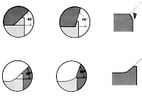
Figure 2: The proper insert geometry for a given application can reduce exiting problems of burrs in steel and stainless steel and can minimize breakout in cast iron.
At the exit stage, the insert is hot, and the chip tears at the top face of the insert, generating tensile forces. In addition, burrs may form at the exit point in steel and stainless steel, and breakout may occur in cast iron (Figure 2). While “cutting air” before the next cutting cycle, the insert encounters no forces, it may have a chance to cool, and it is subject to thermal cycling. This is the most dangerous phase of the process.
When profiling, cutting forces vary much more widely in magnitude and direction. Different portions of the cutting edge come into play as the cut progresses, since more of the insert’s available edge actually does the cutting.
Today’s Geometries
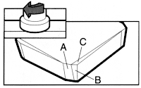
Figure 3: Reinforced corners and edges (A, B, and C) of contemporary milling inserts help extend edge life.
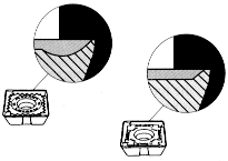
Figure 4: Cutaways show two varieties of positive rake that may be pressed into a steel milling insert for light cutting (left) or medium cutting (right).
Let’s take a closer look at the geometric features of a direct-pressed, positive-rake milling insert. Figure 3 shows the key features on a corner and along the edge of an insert for milling steel. Both the corner and the cutting edge usually are reinforced for edge security.
Figure 4 shows typical positive-rake insert geometries, which are pressed into the top surface with complex punch designs. The main value of positive-rake milling is to reduce cutting forces; the cutting action is more akin to slicing, rather than the tearing action in zero- or negative-rake milling. For steels, cast iron, and stainless steels, positive-rake angles up to +17° have been employed successfully. The basic rationale for positive-rake milling is that cutting power requirements decrease by 1.3% per degree of positive rake and that cutting forces can diminish by 10% to 40%. This reduction in power and forces can be applied wherever it most benefits the process economics—the cost of running the part. This includes saving energy, running the operation harder, or reducing cutting forces on a delicate workpiece, long tool overhang, or a less securely clamped workpiece.
The positive rake also directs axial cutting forces toward the center of insert support, thus improving insert life. For heavy milling, less-positive insert geometries offer increased strength and impact resistance.
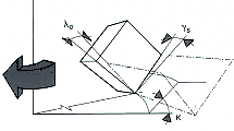
Figure 5: The key angle for controlling cutting forces is the orthogonal rake angle.
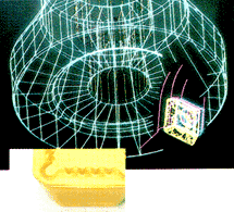
Figure 6: The lobe in the corner of this roughing insert for a square-shoulder cutter serves as a chip deflector.
When estimating cutting forces, the operative rake angle is the orthogonal rake angle (Figure 5). It is a function of the axial inclination of the insert in the cutter, the entering angle, and the pressed-in insert rake angle. It is best described as the rake angle that the chip “sees.”
Chip deflectors (Figure 6) serve two functions: to direct the chip away from the cutter and the interface for efficient disposal and less wear and tear on the cutter; and to direct some of the cutting forces toward the insert seat.
Raised geometry features take a variety of forms. Sinuous designs, small bosses, or bumps may be used. Whatever the specific geometry, the function is to minimize contact with the insert, thereby encouraging cooler milling. The cooler the insert runs, the longer it lasts. Cool running also benefits many workpieces that could harden, lose shape, or lose dimensional accuracy if overheated.
Positive-rake inserts have proven effective in controlling and reducing cutting forces in all three basic geometry configurations: positive axial rake/positive radial rake, negative axial rake/negative radial rake, and positive axial rake/negative radial rake (Figure 7).
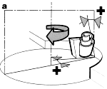
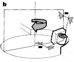
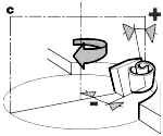
Figure 7: Even with negative cutter-seat angles, positive-rake inserts can create a net positive-rake angle to the working surface and chip. The three basic geometry configurations are positive/positive (a), negative/negative (b), and positive/negative (c).
There are three basic classes of top-surface geometry. For light, low-force milling and finish milling, the rake angle is relatively high and edge rounding is relatively low, creating a “sharper” edge. For heavy milling and roughing, the rake angle is low and edge rounding is more pronounced, creating a stronger edge. For medium milling, both the rake angle and edge rounding are moderate.
To optimize virtually any milling operation, the insert can be matched to specific conditions, such as type of cut, machine rigidity and power, workpiece material, setup, and workpiece strength and stability. To simplify insert selection and use, Sandvik has begun directly pressing the reference code, geometry, grade information, and edge identification into its inserts. A guide has been developed to help identify the appropriate insert for a job and provide material-specific cutting data.
Case In Point
Recent field experience helps establish the practical value of these developments in insert geometries. An automaker was trying to improve the efficiency of a rough- and finish-milling operation on the joint face of the cylinder head of a cast-iron engine block. He wanted to eliminate edge breakout that occurs when pArticles of cast-iron components break out around design features, typically due to cutting pressure. The original plan was to machine the part at a high surface speed with silicon-nitride inserts in a negative-rake presentation. However, problems resulted from workpiece movement and edge breakout due to high cutting forces coupled with limited ability to clamp the part.
The solution was to reduce cutting speeds and machine with positive-rake, light-milling inserts. By using these inserts in a facemill with negative-rake insert pockets, the effective rake was changed to positive and the cutting forces were dramatically reduced. Edge breakout was reduced to the point that edge indexing frequency decreased 25%. Quality was improved, and workpiece movement due to cutting forces was eliminated altogether.
As metalworking becomes more capital-intensive, the focus is shifting toward improving the financial performance of “big-ticket” assets such as CNC mills. Today’s milling inserts, which can allow the operator to run the machine 20% faster and change inserts 35% less frequently, can exert great leverage in improving the process economics of milling equipment. The trick is to convert the potential for longer edge life and better productivity to higher productive capacity and improved return on capital employed on a $500,000 CNC machining center. Edge life is especially important: The real benefit of edge-life improvement kicks in when the insert can be run harder to boost throughput. A good rule of thumb when a new insert outlasts another is to raise the machining data to the point where edge life is the same as before. In other words, convert an edge-life gain to a capacity gain. That will do more for the bottom line—and that’s where it’s at.
About the Author
Ken Booker is product manager, milling and drilling, at Sandvik Coromant Co., Fair Lawn, NJ.
Related Glossary Terms
- chatter
chatter
Condition of vibration involving the machine, workpiece and cutting tool. Once this condition arises, it is often self-sustaining until the problem is corrected. Chatter can be identified when lines or grooves appear at regular intervals in the workpiece. These lines or grooves are caused by the teeth of the cutter as they vibrate in and out of the workpiece and their spacing depends on the frequency of vibration.
- computer numerical control ( CNC)
computer numerical control ( CNC)
Microprocessor-based controller dedicated to a machine tool that permits the creation or modification of parts. Programmed numerical control activates the machine’s servos and spindle drives and controls the various machining operations. See DNC, direct numerical control; NC, numerical control.
- cutting force
cutting force
Engagement of a tool’s cutting edge with a workpiece generates a cutting force. Such a cutting force combines tangential, feed and radial forces, which can be measured by a dynamometer. Of the three cutting force components, tangential force is the greatest. Tangential force generates torque and accounts for more than 95 percent of the machining power. See dynamometer.
- facemill
facemill
Milling cutter for cutting flat surfaces.
- facemilling
facemilling
Form of milling that produces a flat surface generally at right angles to the rotating axis of a cutter having teeth or inserts both on its periphery and on its end face.
- flat ( screw flat)
flat ( screw flat)
Flat surface machined into the shank of a cutting tool for enhanced holding of the tool.
- gang cutting ( milling)
gang cutting ( milling)
Machining with several cutters mounted on a single arbor, generally for simultaneous cutting.
- machining center
machining center
CNC machine tool capable of drilling, reaming, tapping, milling and boring. Normally comes with an automatic toolchanger. See automatic toolchanger.
- metalworking
metalworking
Any manufacturing process in which metal is processed or machined such that the workpiece is given a new shape. Broadly defined, the term includes processes such as design and layout, heat-treating, material handling and inspection.
- milling
milling
Machining operation in which metal or other material is removed by applying power to a rotating cutter. In vertical milling, the cutting tool is mounted vertically on the spindle. In horizontal milling, the cutting tool is mounted horizontally, either directly on the spindle or on an arbor. Horizontal milling is further broken down into conventional milling, where the cutter rotates opposite the direction of feed, or “up” into the workpiece; and climb milling, where the cutter rotates in the direction of feed, or “down” into the workpiece. Milling operations include plane or surface milling, endmilling, facemilling, angle milling, form milling and profiling.
- milling cutter
milling cutter
Loosely, any milling tool. Horizontal cutters take the form of plain milling cutters, plain spiral-tooth cutters, helical cutters, side-milling cutters, staggered-tooth side-milling cutters, facemilling cutters, angular cutters, double-angle cutters, convex and concave form-milling cutters, straddle-sprocket cutters, spur-gear cutters, corner-rounding cutters and slitting saws. Vertical cutters use shank-mounted cutting tools, including endmills, T-slot cutters, Woodruff keyseat cutters and dovetail cutters; these may also be used on horizontal mills. See milling.
- profiling
profiling
Machining vertical edges of workpieces having irregular contours; normally performed with an endmill in a vertical spindle on a milling machine or with a profiler, following a pattern. See mill, milling machine.
- radial rake
radial rake
Also known as the tool back rake, the angle between the tooth face and the radial plane through the tool point.
- rake
rake
Angle of inclination between the face of the cutting tool and the workpiece. If the face of the tool lies in a plane through the axis of the workpiece, the tool is said to have a neutral, or zero, rake. If the inclination of the tool face makes the cutting edge more acute than when the rake angle is zero, the rake is positive. If the inclination of the tool face makes the cutting edge less acute or more blunt than when the rake angle is zero, the rake is negative.
- slotting
slotting
Machining, normally milling, that creates slots, grooves and similar recesses in workpieces, including T-slots and dovetails.
- stainless steels
stainless steels
Stainless steels possess high strength, heat resistance, excellent workability and erosion resistance. Four general classes have been developed to cover a range of mechanical and physical properties for particular applications. The four classes are: the austenitic types of the chromium-nickel-manganese 200 series and the chromium-nickel 300 series; the martensitic types of the chromium, hardenable 400 series; the chromium, nonhardenable 400-series ferritic types; and the precipitation-hardening type of chromium-nickel alloys with additional elements that are hardenable by solution treating and aging.
